Continue to Site

Welcome to our site!

Electro Tech is an online community (with over 170,000 members) who enjoy talking about and building electronic circuits, projects and gadgets. To participate you need to register. Registration is free. Click here to register now.

  • Welcome to our site! Electro Tech is an online community (with over 170,000 members) who enjoy talking about and building electronic circuits, projects and gadgets. To participate you need to register. Registration is free. Click here to register now.

Help needed diagnosing and repairing a PC engine LT, currently looking at oscillator

Status
Not open for further replies.

soop

New Member
Hello all. I'm currently trying to repair a damaged PC engine LT (a portable games console circa 1991)I got a few years ago. The thing had 10+ lifted pads and three lifted traces from corrosion from bad caps when I got it, and the first step was to clean it and repair the traces and pads as best I could using some copper and a high temperature two part epoxy, then replace the capacitors. Of course it would be amazing if that had fixed the console, but things are never so simple. I've double checked the capacitors, and I'm (90%) confident that they have connectivity where they need to have connectivity, but we still have no video out and no sound. I've checked the voltage and ground to the CPU and graphics chips, and both are correct. I've also checked the connectivity from the chip to the external bus, which, while not linked to the screen, is nearby and traverses the motherboard from the chip. There's also a fairly good 1-1 correspondence from the GPU pins to the pinout of the bus.

The next thing I attempted to measure was the oscillator, and here, I'm not seeing what I'm expecting. I see a wave, though it's not perfectly square (straight up or down, then a slope immediately back to 0v, flat line, repeat), but the issue is the frequency is not what I was expecting. I'd expect to see the pattern at 50ns, but instead I'm seeing it at 5ms. The oscillator should provide a 3.579545 MHz clock signal (NTSC video).

I'm a complete newbie having never used an oscilloscope before, so it may be that I'm doing something wrong, but the signal is well defined at that range, so it looks like there's an issue. How would I go about diagnosing the issue from here?
 
Are you using a x10 probe?, if you're using a x1 probe then that commonly upsets the oscillator, often stopping it entirely - due to the extra capacitance.

So set your scope probe to x10, or if it's not switchable, get one that is.
 
ah it was set to 1x. I'll try it again at 10x

*edit* ok, I've re-probed at 10x, and I'm seeing a much more square wave, but it's still at 50ms rather than 5ns. The voltage range is also at +/-1v or so which is improved. But not the frequency expected.
 
Last edited:
Are you on the correct crystal?, it's quite common to have more than one crystal - and presumably an NTSC frequency crystal would only be as part of the composite/rf modulator.
hmmm... so the oscillator says 3579.545 on it, but I've just realised something. It's right by an AV input (the device can be used as an external composite monitor), and that isn't being used currently. I'm not sure if a lack on input signal would cause the anomaly. I'll just check to see if there's another oscillator.
there is one marked 4.0akss1f and another marked 21.47kss 1b.

The 3579.545 matches the NTSC frequency, and is the only one of that rating on the PCB, and I can't imagine they'd duplicate the component. Would the monitor not being connected result in a lower clock frequency than expected?

It shouldn't do, but I wouldn't expect that to stop it working, if you're not using a composite output.
 
so the oscillator says 3579.545 on it, but I've just realised something. It's right by an AV input (the device can be used as an external composite monitor),

That crystal could be part of the colour decoder for the composite input, rather than anything to do with the CPU side.

Either of the others could easily be the CPU clock source.
 
ok, something really bizarre happened. I decided to order a new crystal, just in case, and try and focus on the audio for the time being. I identified the L/R audio pins on the correct chip, set my oscilloscope to A/C, and touched the probe to one of those pins. I get the exact same square wave I was getting from the oscillator, without changing any of the other settings. I think it's about 8hz or so. And then when I connect the probe to ground, it disappears. disconnect from ground, it comes back.

I'm not quite sure how to progress from here
 
20230306_142830.jpg
20230424_203443.jpg
 

Attachments

  • 20230415_163237.jpg
    20230415_163237.jpg
    1.9 MB · Views: 246
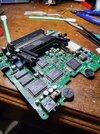
ok, so the third pic didn't end up as clear as I'd like - and unfortunately, I didn't the a pic with the cartridge slot removed. But in the second pic the oscillator is the silver rectangle in the bottom left quarter of the board near the plastic dial of the potentiometer. The CPU and chip responsible for audio is the IC within the "C" of the cart slot. And there are two discreet power inputs on the top and bottom of the board, in line with the back section of the cart slot. There's also a headphone jack on the left facing side of the top left quarter of the board
 
Last edited:
Top left of the second photo, is that a rusty power switch? What are the symptoms when powered on?
that's the power switch, there's some light surface rust, but nothing awful. The symptoms, the power LED comes on, every IC gets 5v but no video, no audio

Also, I'd just mention that the first pic was taken before I attempted to repair, so you can see a missing trace to the IC in the top left. That has been repaired now
 
Where on the board are you connecting the scope probe ground clip?
the closest ground I could reliably connect to was the ground of the aux jack for the composite input, or alternately the ground in the outer corner of the same quadrant. I considered soldering a more reliable lead for the crocodile clip to bite onto, but I haven't yet
 
Status
Not open for further replies.

Latest threads

New Articles From Microcontroller Tips

Back
Top