learning
Member
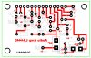
Audio Amplifier LA4440 IC
Can you tell me the correctness of the circuit diagram? As I can buy it from the market but I want to make it by myself for my satisfaction. If anyone can help me I will be very much happy for your generosity!
Thank you !
Can you tell me the correctness of the circuit diagram? As I can buy it from the market but I want to make it by myself for my satisfaction. If anyone can help me I will be very much happy for your generosity!
Thank you !
Attachments
Last edited: