Continue to Site

Welcome to our site!

Electro Tech is an online community (with over 170,000 members) who enjoy talking about and building electronic circuits, projects and gadgets. To participate you need to register. Registration is free. Click here to register now.

  • Welcome to our site! Electro Tech is an online community (with over 170,000 members) who enjoy talking about and building electronic circuits, projects and gadgets. To participate you need to register. Registration is free. Click here to register now.

help need:38khz ir transmitter using multivibrator

Status
Not open for further replies.

aruna1

Member
hello
i was wandering can i use simple multivibrator circuit to generate 38khz signal to use as a IR transmitter for TSOP1738?

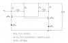
i did some readings and calculations and came up with resistor and transistor values that gives 38khz.
but since i don't have a oscilloscope i don't know whether this circuit will work.

and most importantly all 38khz IR transmitter circuits on internet are based on NE555.i wonder why nobody use a multivibrator?

calculations are based on article
Multivibrator - Wikipedia, the free encyclopedia

any help would be great
thanks

here is my circuit diagram
**broken link removed**
 

Attachments

  • multivibrator 38khz.JPG
    multivibrator 38khz.JPG
    27.8 KB · Views: 758
and most importantly all 38khz IR transmitter circuits on internet are based on NE555.i wonder why nobody use a multivibrator?
The NE555 is a multivibrator with the addition of only a few components! It's a small low cost single chip solution that can easily be wired as a number of different functions with a minimum of design effort.
 
I presume you're not aware that TSOP's are designed for data, and NOT continuous carrier? - with a continuous carrier the TSOP turns it's gain down to try and prevent the continuous interference.
 
I presume you're not aware that TSOP's are designed for data, and NOT continuous carrier? - with a continuous carrier the TSOP turns it's gain down to try and prevent the continuous interference.

well actually there are TSOP ir modules that supports continoues signals.ex TSOP 1738 it does not low its gain when continoues 38khz signal is available.chk the datasheet
thanks

anyway do you think ths multivbrator thing will work?
 

Attachments

  • TSOP1738.pdf
    214.5 KB · Views: 360
Last edited:
well actually there are TSOP ir modules that supports continoues signals.ex TSOP 1738 it does not low its gain when continoues 38khz signal is available.chk the datasheet
thanks

As long as you've got one that does, I've never seen one, and never heard of one - but obviously it's not for remote control.

anyway do you think ths multivbrator thing will work?

Yes, of course - an astable multivibrator is a VERY old tried and tested device.

Four points though:

1) D1 and D2 aren't needed for a 3V supply, only once you get to about 9V or so.

2) The resistors seem very low values, it makes more sense to be much higher.

3) The IR LED should be directly in the collector of one of the transistors, saving an extra transistor to drive it - although for longest range you may need a driver anyway.

4) You don't need it to be 50/50 mark/space ratio - short high current pulses with a longer space time increases range as well, with no increase in power consumption.
 
well i didnt get that one,can you explain little bit?

Conventionally the LED will be ON 50% of the time, and OFF 50% of the time, 50/50 ratio - but if you make the ON time 20%, and the OFF time 80% you can increase the current fed to the LED (by two and a half times as much) and increase the range. This doesn't increase power consumption, so it's a range increase for 'free'.
 
well actually there are TSOP ir modules that supports continoues signals.ex TSOP 1738 it does not low its gain when continoues 38khz signal is available.chk the datasheet
thanks

anyway do you think ths multivbrator thing will work?

hi,
I have just read your datasheet and the way I read it, says data bursts are required, not continuos transmission. ?
The d/s is a little misleading in saying continuous.
 

Attachments

  • AAAimage01.gif
    AAAimage01.gif
    21.3 KB · Views: 391
Last edited:
hi,
I have just read your datasheet and the way I read it, says data bursts are required, not continuos transmission. ?
The d/s is a little misleading in saying continuous.

well actually i have used TSOP1738 in one of campus my project.those days i didnt know about continoues data transmission,all i knew was it low its output when recieving 38khz signal.i used a continues 38khz ir signal (used NE555).and it worked
 
well actually i have used TSOP1738 in one of campus my project.those days i didnt know about continoues data transmission,all i knew was it low its output when recieving 38khz signal.i used a continues 38khz ir signal (used NE555).and it worked

Over what distance? - they don't stop working, they just drastically reduce the gain, assuming it's unwanted interference, to prevent the receiver been swamped.
 
My 0.02

hello
i was wandering can i use simple multivibrator circuit to generate 38khz signal to use as a IR transmitter for TSOP1738?


all 38khz IR transmitter circuits on internet are based on NE555.i wonder why nobody use a multivibrator?

1. yes, but you'd have to modulate it as required by the TSOP, beware m-vib modulation is quirky

2. Because it's easier to use 555, it's easier to modulate

Are you sending data over NIR? Or do you just want to make something like a IR beam-break detector?
 
My 0.02


1. yes, but you'd have to modulate it as required by the TSOP, beware m-vib modulation is quirky

2. Because it's easier to use 555, it's easier to modulate

Are you sending data over NIR? Or do you just want to make something like a IR beam-break detector?

i dont send any data,just a beam break detector(to use as a simple remote)
 
Over what distance? - they don't stop working, they just drastically reduce the gain, assuming it's unwanted interference, to prevent the receiver been swamped.
well it worked about 1.5 meters.and I'm sure it didn't reduce gain.(coz i used interrupt to detect Ir signal so if it reduce gain then interrupt would be triggered unnecessarily)
 
well it worked about 1.5 meters.and I'm sure it didn't reduce gain.(coz i used interrupt to detect Ir signal so if it reduce gain then interrupt would be triggered unnecessarily)

I should hope it did work at 1.5 meters, that's an incredibly short range - and the range WILL have been drastically shortened - I see no relevence of you using interrupts or anything else. The ONLY way to know if the gain has been reduced is to measure how far away it works - on normal pulsed signals (as designed) 15 meters is easy to do.
 
If it's a beam-break detector, that's easy. Power an LED with a frequency, be it 9, 38 or whatever kHz. Use a 555, an LED, just 2 resistors and one capacitor for that circuit.

Then have a PV photo diode, connected in 'PC mode' feeding current through a resonant circuit tuned to your frequency, the res circuit rejects ambient light etc. Across the res cct. will be a AC signal that you can amplify if need be. The AC signal (from a few mV to a few V) can be fed into a 567 tone detector, which goes logic low when it hears your LED singing.

Make the 567 and the oscillator variable, because the tuned circuit might not be adjustable easily enough if it's a low frequency.

You can choose whatever frequency you like for your res circuit, but remember the 567 only goes up to 500 kHz(?) and too low, the res-circuit is clumsy.
 
Last edited:
If it's a beam-break detector, that's easy. Power an LED with a frequency, be it 9, 38 or whatever kHz. Use a 555, an LED, just 2 resistors and one capacitor for that circuit.

Then have a PV photo diode, connected in 'PC mode' feeding current through a resonant circuit tuned to your frequency, the res circuit rejects ambient light etc. Across the res cct. will be a AC signal that you can amplify if need be. The AC signal (from a few mV to a few V) can be fed into a 567 tone detector, which goes logic low when it hears your LED singing.

Make the 567 and the oscillator variable, because the tuned circuit might not be adjustable easily enough if it's a low frequency.

You can choose whatever frequency you like for your res circuit, but remember the 567 only goes up to 500 kHz(?) and too low, the res-circuit is clumsy.

hmm that is bit lengthy process
 
hmm that is bit lengthy process

I don't think so, 2, maybe 3 IC's at the most, one inductor. No transistors. About 6 resistors.

**broken link removed**

Can maybe omit the amplifier if only 2 metres apart.
 
Last edited:
hmm that is bit lengthy process

hi,
If all you need is a beam break over a distance of 1.5mtr, a 555 /transistor driving a IR emitter being detected by a IR diode followed by an 'ac' coupled amp, with a simple bandpass circuitry is all that is needed.

If ambient light is a problem use a simple tube collimator over the detector.
 
If it's a beam-break detector, that's easy. Power an LED with a frequency, be it 9, 38 or whatever kHz. Use a 555, an LED, just 2 resistors and one capacitor for that circuit.

Then have a PV photo diode, connected in 'PC mode' feeding current through a resonant circuit tuned to your frequency, the res circuit rejects ambient light etc. Across the res cct. will be a AC signal that you can amplify if need be. The AC signal (from a few mV to a few V) can be fed into a 567 tone detector, which goes logic low when it hears your LED singing.

Make the 567 and the oscillator variable, because the tuned circuit might not be adjustable easily enough if it's a low frequency.

You can choose whatever frequency you like for your res circuit, but remember the 567 only goes up to 500 kHz(?) and too low, the res-circuit is clumsy.

what is PV phote dioade and 'PC mode' ?
 
Status
Not open for further replies.

Latest threads

New Articles From Microcontroller Tips

Back
Top