Continue to Site

Welcome to our site!

Electro Tech is an online community (with over 170,000 members) who enjoy talking about and building electronic circuits, projects and gadgets. To participate you need to register. Registration is free. Click here to register now.

  • Welcome to our site! Electro Tech is an online community (with over 170,000 members) who enjoy talking about and building electronic circuits, projects and gadgets. To participate you need to register. Registration is free. Click here to register now.

help need:38khz ir transmitter using multivibrator

Status
Not open for further replies.
In my opinion the 4046 is superior to the NE567.

Haven't you designed the transmitter yet?

Google for CMOS oscillator.

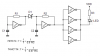
Calculate the component values for a two gate oscillator.

Use a 74HC04 which will work down to 2V.

Buffer the oscillator with four paralleled gates.

Connect the output to the LED via a suitable series resistor.

Pleas post the schematic you've drawn on this forum. Don't worry if it's wrong, we'lll go easy on you. :D
 
well i postponed transmitter for a while until i get working solution and began making rest of circuits.I'm making a remote controller for my rooms ceiling fan using PIC12F675.since you have suggested a solution i will get back to transmitter part.
and thanks everyone for all your help
 
If you're using a PIC then you shouldn't need a PLL, it's possible to implement it in software.

You could use a simple PIC for the transmitter too, try the PIC12F509, the cheapest PIC you can buy.
 
well i postponed transmitter for a while until i get working solution and began making rest of circuits.I'm making a remote controller for my rooms ceiling fan using PIC12F675.since you have suggested a solution i will get back to transmitter part.
and thanks everyone for all your help

So why are you messing with multivibrators and talks of PLL's?.

You can get low voltage versions of the PIC's that run happily on 3V, use an 8 pin one of those to generate the 38KHz in suitable bursts (use my tutorials if you like), and feed an NPN transistor feeding an IR LED. THis will give you an easy 10 meters plus range.

For the receiver, use a TSOP feeding another 8 pin PIC that receives the IR code, checks it, and loops - with a timeout if the IR data is missing.
 
PIC s are expensive here.and only available 8pin PIC is 12F675

and i have lerned lot with discussion
 
Last edited:
ahh PIC for the reciver.
Yes, and for the transmitter.

You should have mentioned that you're going to use a PIC as it would have saved the last three pages.

Nigel's tutorials are good.


Some other good tutorials covering the simpler PICs e.g. PIC12F509.
Gooligum Electronics

PIC s are expensive here.and only available 8pin PIC is 12F675

and i have lerned lot with discussion
The 12F509 is much cheaper and should be easier to get hold of, anything more powerful (e.g. 12F675) just to flash an LED is overkill.

I'm from srilanka
Don't you have Farnell or RS components over there?

12F675 works from 3.3v
The 12F509 works from 2V, so does the 12F675.
 
Last edited:
Yes, and for the transmitter.

You should have mentioned that you're going to use a PIC as it would have saved the last three pages.

Nigel's tutorials are good.


Some other good tutorials covering the simpler PICs e.g. PIC12F509.
Gooligum Electronics


The 12F509 is much cheaper and should be easier to get hold of, anything more powerful (e.g. 12F675) just to flash an LED is overkill.


Don't you have Farnell or RS components over there?


The 12F509 works from 2V, so does the 12F675.
farnell is availble but nearl 125km away from my location.going there for only for a PIC....hmmm
 
Don't they do delivery?

Here in the UK they'll deliver for free.
 
Have you tried ebay?
 
i went to buy 74HC04 but they were out of stock.so i bought 74HC14 and assembled following circuit.it seems working.but power is too low.i guess i have to do that parallel remaining gate thing here too.anyway can someone tell me how this parallel gate thing works?

**broken link removed**
 
can someone tell me how this parallel gate thing works?
Simple, connect all the inputs and outputs of the remaining five gates together and connect the inputs to the output of your oscillator.

The problem with the Schmitt trigger oscillator is that it tends not to be very stable.

Do you have a frequency counter or oscilloscope?

You could make part of the resistor a trimmer, for example, make R = 27k, connect a 10k trimmer in series and tune to the correct frequency using a low capacitance trimmer tool.

IR remote controll ICs also tend to require pulses of the 38kHz signal to work and it's possible to generate these using a CMOS oscillator.
 
Last edited:
Simple, connect all the inputs and outputs of the remaining five gates together and connect the inputs to the output of your oscillator.

The problem with the Schmitt trigger oscillator is that it tends not to be very stable.

Do you have a frequency counter or oscilloscope?

You could make part of the resistor a trimmer, for example, make R = 27k, connect a 10k trimmer in series and tune to the correct frequency using a low capacitance trimmer tool.

IR remote controll ICs also tend to require pulses of the 38kHz signal to work and it's possible to generate these using a CMOS oscillator.

no no i like to know the theory of making them parallel.(why do we need to parallel them)

i use a preset as R

i don't have a oscilloscope

and IR receiver module I use(HRM3800/TSOP1738) does not require pulses 38khz.it supports continues signals.
 
Last edited:
and IR receiver module I use(HRM3800/TSOP1738) does not require pulses 38khz.it supports continues signals.

We've already been through this - according to the datasheet it doesn't support continuous signals, it will drastically reduce it's range in their presence as with other TSOP's.
 
I have an idea which will produce pulses of 38kHz.

R1 and C1 controls the repetition rate and R2 and C2 controls the IR modulation frequency.

D1 must be a small signal Schottky or germanium diode, silicon has too higher voltage drop, try BAT85.
 

Attachments

  • IR burst Schmitt.PNG
    IR burst Schmitt.PNG
    11.5 KB · Views: 453
Last edited:
D1 must be a small signal Schottky or germanium diode, silicon has too higher voltage drop, try BAT85.

My suggestion, if can't get the diode, do without it. Connect lower end of C2 instead to the output of the first IC. It's a bodge, I know, but it'd work enough to periodically interrupt the 2nd oscillator.

Whether the interruption will be long enough for the TSOP is another matter.
 
Last edited:
Status
Not open for further replies.

Latest threads

Back
Top