Continue to Site

Welcome to our site!

Electro Tech is an online community (with over 170,000 members) who enjoy talking about and building electronic circuits, projects and gadgets. To participate you need to register. Registration is free. Click here to register now.

  • Welcome to our site! Electro Tech is an online community (with over 170,000 members) who enjoy talking about and building electronic circuits, projects and gadgets. To participate you need to register. Registration is free. Click here to register now.

Help me with instrumentation amplification

Status
Not open for further replies.

Unicorn_tech

New Member
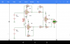
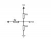
Good day engineers. I'm building a resistivity meter that measures the resistivity of the earth. To make this automated, I'm using pic microcontroller to control the system. But it is needed of the device to be able to measure the spontaneous potential of the earth. This forum has been so helpful with beautiful minds at help. I was able to utilize three resistors and some set of instructions to measure the negative voltage of the earth. But to test it with the Earth, it is not really sensitive. So, doing some research, I came up with a circuit diagram of an instrumentation amplifier. But the problem I'm having is that, the instrumentation amplifier has three pinout to touch the earth surface instead of two. Please help me with a very good idea of how to be able to make this happen. Attached to this post is the circuit diagram of the instrumentation amplifier. With two pinout to the microcontroller and three measuring floating voltages from the ground. But I need just two to the ground. Thanks great minds.
 

Attachments

  • Screenshot_2018-08-29-09-07-22.png
    Screenshot_2018-08-29-09-07-22.png
    72.2 KB · Views: 173
I need an instrumentation amplifier that is sensitive enough to measure the natural voltage the earth surface generates (I.e spontaneous potential of the Earth)
 
Below is the diagram of how the resistors were arranged to measure both positive and negative voltages. I got this idea from this forum. This circuit diagram is connected to the operational amplifier and the ADC output is connected to the pic microcontroller.
 

Attachments

  • IMG_20180829_093723_284.JPG
    IMG_20180829_093723_284.JPG
    16.9 KB · Views: 179
Last edited:
a resistivity meter that measures the resistivity of the earth.
to measure the spontaneous potential of the earth.
to measure the negative voltage of the earth
So I am a little confused. Are you measuring voltage or resistance? If you use a multi-meter and place the probes into the ground, what setting do you have on the meter? (voltage or resistance? AC or DC)

why? Are you measuring how much water is in the dirt for the plants?
Is your circuit powered by batteries?
I want to measure the natural floating voltage the earth is producing, the circuit is powered by battery. What I need instrumentation amplifier for is to increase the voltage gain.
 
Last edited:
The diagram attached is the physics behind the instrumentation. The part labeled MN is connected to a very sensitive and high impedance Voltmeter that can measure as low as -200mV. So, I want to build that voltmeter
 

Attachments

  • images-13.jpg
    images-13.jpg
    12.4 KB · Views: 167
Voltage is normally relative to another potential. This is normally Ground. What will your measurement be relative to?

Mike.
 
You need to start all over. Here's a paper: https://dranetz.com/wp-content/uploads/2014/02/ground-resistance-testing-principle.pdf

Key parts:
Electrode spacing
AC excitation
Note measured values of 20 V and 1 A
They did use a square wave excitation.

You don't want to use DC in soil, because you will plate out "something" and make a battery eventually.

Next question is what to measure: RMS, Peak or it may not matter as lomg as I and V are measured the same way.
 
Here is the "tester" used in the .PDF from post #10.
https://www.aemc.com/userfiles/files/resources/usermanuals/Ground-Testers/3640_EN.pdf

You do not need a diff-amp. You are using a battery that gets you isolated from everything.
I don't see why you need high impedance. But OK.
It looks like you need a simple op amp circuit non-inverting. Gain of 10 or have a gain of 1/10 switch.
Signal goes into the (+) input to keep the input impedance high. (add input protection resistor and diodes)
Sorry on this computer I do not have a way to draw a schematic.

You might not need the amplifier if you inject that much power into the Earth.
From Post #4:
Probe-1: protection resistor of 100k and two diodes to protect the PIC's ADC input.
Probe-2: use two matched across the power supply to make a 1/2 supply voltage. 10K & 10K ohms. Use this 1/2 supply voltage as probe-2.
How does this work? If you short the two probes the PIC will measure a voltage in the middle of its ADC range. If the voltage on the probes is + the number from the ADC will to up, if the voltage is negative the number will drop. (On a 5V PIC center=2.5V) You can measure +/- 2.5V full scale.
Thanks so much for this reply, I'm using a sine wave inverter to inject AC current into the ground and rectifier and capacitor to reduce the current and noises respectively. I also used the resistors arrangement to measure negative and positive. But the problem is that I'm getting erratic reading from the ADC. I'm looking for a way of making it more sensitive and stable. I don't if I add a capacitor to the input, the noises will be attenuated
 
You need to start all over. Here's a paper: https://dranetz.com/wp-content/uploads/2014/02/ground-resistance-testing-principle.pdf

Key parts:
Electrode spacing
AC excitation
Note measured values of 20 V and 1 A
They did use a square wave excitation.

You don't want to use DC in soil, because you will plate out "something" and make a battery eventually.

Next question is what to measure: RMS, Peak or it may not matter as lomg as I and V are measured the same way.
I used ACS712 for the I, but I need a circuit that is sensitive enough to measure earth voltage as low as -200mV
 
Can someone explain what is going to be measured by this device? And how?

Mike.
It measure the earth resistivity. P=R x G. Where G is the geometric factor (electrodes arrangement), R= DV/I (I is current response of the ground, DV is the potential difference) and P is the resistivity
 
The AC current will be injected into the ground through A and B terminals. While the circuit diagram (instrumentation amplifier) below is connected to M and N which measure the Natural voltage produced by the earth as low as -200mV. This instrumentation amplifier is connected to a voltage divider with 3 resistors. This voltage divider is then connected to the ADC of the pic microcontroller.
 
Status
Not open for further replies.

Latest threads

New Articles From Microcontroller Tips

Back
Top