Electro Tech is an online community (with over 170,000 members) who enjoy talking about and building electronic circuits, projects and gadgets. To participate you need to register. Registration is free. Click here to register now.
Welcome to our site! Electro Tech is an online community (with over 170,000 members) who enjoy talking about and building electronic circuits, projects and gadgets. To participate you need to register. Registration is free. Click here to register now.
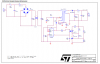
The transformer seems to be hooked up differently from what I would expect, is it correct? It appears that the phasing dots are boosting each other, or are they bucking, or does it have to do with current limiting,
Thank You,
Kinarfi
It's not a transformer, it's a common-mode choke to reduce common-mode noise. Thus common-mode signals see the inductance of the choke since they are in-phase. Normal-mode signals (the input current) are out-of phase and thus do not see the inductance (it acts like a transformer with equal primary and secondary currents).
Mike the output is isolated, it's a switch mode supply, they're pretty much all designed like this. Watching what you touch when it's energized is a definite requirement.
Mike the output is isolated, it's a switch mode supply, they're pretty much all designed like this. Watching what you touch when it's energized is a definite requirement.
If the value of the capacitor is 12n or lower I'd touch a wet finger to it with absolute certainty nothing bad would happen. If as I guess it's to give the secondary circuit some very slight ground reference the value should be low.
Been fine so far =) Seriously, look at the possible currents from a low value capacitor through human body models. If it's under 12n you shouldn't even be able to feel it, and you might start to notice it if a phase condition caused you and the circuit to be 180 degrees out of phase. Anything to say technically or are you just trying to be inflammatory?
The typcical human model is 1.2k resistance to ground, and 100p of capacitance. Do the math, what's that dead shorted to mains AC (in the US)? Lethal. Do it again with double the mains voltage (to compensate for a possible freak internal capacitance phase reversal) and run the numbers again with a 12n cap in series. Not even a full mA
I am not sure what C4 has to do with grounding or not but in a power supply its the secondary isolation that matters. My only concern with this circuit is that its not a complete diagram. Until we can see the whole circuit most of this is going to be speculation.
Who's been coaching Kinarfi on posting schematics anyway? I only know one other person here who cant post complete work or follow through on his work.
As far as human conductivity goes I think that under most circumstances as long as the person working on the live circuit is standing on a dry floor and preferably wearing clean shoes they have almost no chance of even feeling a tingle off of the DC side of the circuit unless they touch two different points at once. And even then if his fingers are dry he will likely just get a tingle that is strong enough to remind him to pay more attention or the last thing he may see is the lights at his work bench browning out as his own lights brownout.
As far as what current level kills that is unique to every single person and their immediate circumstances. If he is young fit and in all around good heath I suspect its going to take a few tens of Ma for many seconds to kill him. But if he is old feeble and has a weak heart or or blood vessel in his brain he may go down quick with just a few Ma.
120VRMS*1.414/1200 = 141mA, more than enough to give you a good buzz or to have you end up with big problems. There is no 12n cap in series. The + terminal is connected directly to the mains power, through the diode bridge.
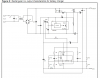
When I started this thread, I was curious about the way the transformer was hooked up, the schematic came from **broken link removed** and here's the full schematic that I started with and another one,too.
Kinarfi
Brownout, I'm not talking about a dead short from mains to the human body model, looks like Mike said C4, I said if it was 12nF I was referring to C7, my mistake in notation as I mistook his mention of C4 as to the only cap I was concerned about which is C7. It's a moot point as there's no value for anything in the schematic, and I'm beginning to think it may be in the schematic because it was meant to be simulated and simulations can't have floating grounds.
I do know what I'm talking about, problem is no one else does
What we have here is a failure to communicate. I will continue living despite your thoughts to the contrary =>
The second schematic shows a ground at the bottom even though that circuit is part of the live line side of things.
The first schematic seems to be conceptually in order though. I think C7 could be considered an optional component but I have seen quite a few SMPS with a small snubber capacitor between the primary and secondary circuits just the same.
I suspect the purpose of C7 is just to provide a path for switching noise to the "cleanest" return path in the circuit. The ground symbols in the 2nd diagram are simply to denote a common potential, and you can think it it as those nodes just being tied together.
Glad to have cleared a few thing up, I hope. Another question about transformer phasing dots, as the current flows from the dot to the other end in the primary, the current in secondary flow from the dot to the other end also, correct? How much of a phase shift is there?
Also with an input of 120 vac the voltage across C4 is 170, correct?
Wait. What transformer are you talking about? I thought we decided the input component was a line filter??? If you mean that one, think of it this way; the current flows into the dot on one side, and then out of the dot on the other side. It doesn't matter which side we are talking about when we say "into" and "out of" Basically, the filter is symetrical, so it works both ways.
This site uses cookies to help personalise content, tailor your experience and to keep you logged in if you register.
By continuing to use this site, you are consenting to our use of cookies.