Continue to Site

Welcome to our site!

Electro Tech is an online community (with over 170,000 members) who enjoy talking about and building electronic circuits, projects and gadgets. To participate you need to register. Registration is free. Click here to register now.

  • Welcome to our site! Electro Tech is an online community (with over 170,000 members) who enjoy talking about and building electronic circuits, projects and gadgets. To participate you need to register. Registration is free. Click here to register now.

Help Identifying an old component

Status
Not open for further replies.
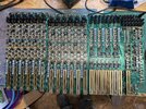
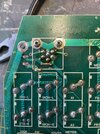
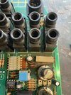
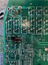
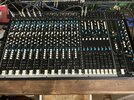
Ahem… so I did indeed speak a little too soon! The power supply is working with all the right voltages coming out the right pins and no fuses are blowing.. but it seems the mixer might have a few issues of its own! Oh well.. easy is boring as they say! I haven’t had time to properly figure out what’s wrong with it but so far, it bums a bit and the leds on the psu go out when it’s plugged into the mixer, the meter lights flicker a bit and the meters don’t show any signal presence but as I said, I haven’t properly tested to see what’s wrong as yet.. but if I do ever get to the bottom of it then great.. if not, fixing the psu was a great learning experience that’s for sure..
Thanks
Pete
 
The capacitors you changed in the PSU were Tantalum types, these are VERY prone to going S/C (which was why most manufacturers stopped using them years ago) - it's quite possible (and very likely) that others are S/C in the rest of the mixer.

Does the mixer have plug-in boards?, if so you could unplug them and see which one is causing the problem (if it is Tantalums, it could easily be more than one as well).
 
Hi again, I’m thinking that continuity this thread here is ok rather than a different section is easier…
So I’ve taken the mixer apart.. there are three boards, each connected to each other with ribbon cables. There are 2 identical boards with six input channels and the third board is the 8 groups and master section that takes the power in. I’ll get some photos up once I’m up and about…
There’s one tantalum capacitors on the back of the two input boards.. and a load of radial electrolytics throughout as well.. I’ve made a list of all the capacitors on those boards, tantalum/electrolytic/ceramic and the little rectangular polyester ones..
I haven’t properly logged the master board as yet but I did notice the pcb track from the power input appears to have been damaged, or so it seems… I’ll get a close up pic of that out also… if that is the cause then that would be easier than capacitor replacement I guess, as there’s lots of those and not loads of room…
Funny though, this mixer was effectively given to me about 15 years ago, working, and after the psu problem, I’m scratching my head as to how the board got scratched like that..
I guess the first thing would be to test the main board and see if it behaves in the way I saw in the beginning, and add the other boards one by one if not…?
Thanks
Pete
 
Ok...here is where I'm at.
There is a pic of the three boards that make up the mixer. The two on the left are two boards of six input channels and the right most board is the master /group section.
After a strip down and a thorough clean (Ahhh the 80's/90's when everyone smoked like a chimney over the desk!)
The mixer powers up totally fine with the group section. So adding the middle input board, again, all is fine. The problem is with the first bank of inputs (left most board). When adding this board, the switch on has a buzz and no lights work and in fact, nothing really works at all, whereas with the working boards, inputs all work, meters, solos etc.
I've listed all the capacitors on each board and there's 1 Tantalum on the underside of the input board and a bunch of radial electrolytics dotted throughout. My temptation is to replace the lot and go from there...Is that a good idea? or too much? I could start with the tantalum and test, followed by the radials...and the the ceramics?
I'm not sure what's going on with the scratch on the power input...the pic looks bad...but the input board works ok, till the other is added..but if I swap the input board so the dodgy one is the only input board then it still freaks out so I'm thinking it isn't a load thing..either way, I wonder if I should fix the tracks?
There's also a mark from heat on the underside which on the top side has a big ceramic block resistor type thing so I'm thinking thats wear and tear, and that board it's on works fine, so that could just be a sign of age?
Either way, it's a good feeling to be getting on top of this thing, having it work, even with half the inputs is a huge step forward for me...your help has been massive!
Thanks
Pete
 

Attachments

  • Whole board.jpg
    Whole board.jpg
    4.8 MB · Views: 193
  • Power input pcb.jpg
    Power input pcb.jpg
    1.7 MB · Views: 189
  • ceramic resistor burn.jpg
    ceramic resistor burn.jpg
    1.6 MB · Views: 178
  • burn.jpg
    burn.jpg
    2.4 MB · Views: 187
Beautiful looking boards :D

What circuit reference is the one Tantalum capacitor?.

Never mind replacing it, just disconnect one end, or remove it entirely, and see if that stops the fault.

Just had a look at the manual, don't worry about the circuit reference - as there's no circuit references on the schematic :D

However, the parts list shows one 2.2uF tantalum on the input boards, though I can't spot it, either on the schematic (which seems to ignore any power to the chips), or on the picture you posted. Can you post a closer picture of where the capacitor is?.

Must admit, I'm a little puzzled as to where just ONE capacitor would be? - only thing I could think of is the phantom power, but that wouldn't cause the problem, and the capacitors on it aren't marked as tantalums. There's two 2.2uF tantalums across the 15V rails on the output board (near the meter), but as removing one of the input boards cures the problem it can't be them.
 
They really are lovely aren’t they?! When I got the board working with the one hood input board it was somehow pleasing to see the relay switch move each time I pressed the solo button… I’ll get a video of it tomorrow..The tantalum is soldered on the underside of the board… it’s the only one. Could explain why it’s hard to find.. I’ll have to get the details tomorrow as it’s Chinese takeaway time! But it should be the 2.2 uf 35v number.. I’ll take a photo tomorrow.. if it’s an underside job, would that mean it’s an afterthought? Or am I being unfair..? I will desolder a leg and see what happens..
While we are at it.. what’s the actual difference between the tantalum’s and say.. a radial electrolytic? I don’t really know the reasons for using different types of capacitors in different places on the board either but I’d love to know..
Thanks
Pete
 
They really are lovely aren’t they?! When I got the board working with the one hood input board it was somehow pleasing to see the relay switch move each time I pressed the solo button… I’ll get a video of it tomorrow..The tantalum is soldered on the underside of the board… it’s the only one. Could explain why it’s hard to find.. I’ll have to get the details tomorrow as it’s Chinese takeaway time! But it should be the 2.2 uf 35v number.. I’ll take a photo tomorrow.. if it’s an underside job, would that mean it’s an afterthought? Or am I being unfair..? I will desolder a leg and see what happens..

At least it's easy to disconnect one leg, and yes it's probably an after thought :D

Not relevant here, but Japanese manufacturers were absolutely terrible about bodging parts all over the board after the main production had been done - and never seemed to bother updating their PCB's accordingly.

Where I used to work we had a VIP visitor from Sony - fairly high up, and he came from Japan - so I asked him why Sony TV's were so poorly designed and constructed. This didn't make him happy :D - so I showed him a current Sony (CRT back then) set, which had 5 or 6 PCB's, loads of connectors, and wires everywhere - plus the usual sprinkling of bit's bodged underneath.

I then showed him a current Tatung set (Tatung were Korean, but designed and built by the old UK Decca team) - this had just one main PCB, plugs to scan coils and CRT base, and a mains lead - that was all. I asked him of his opinion of the relative manufacturing costs of the two sets? - any answer he made was in Japanese (and may have been rude :D) but I think he got the point.

So no problem with one bodged on capacitor.

While we are at it.. what’s the actual difference between the tantalum’s and say.. a radial electrolytic? I don’t really know the reasons for using different types of capacitors in different places on the board either but I’d love to know..
Thanks
Pete

Electrolytic's fail, but tantalums are even worse - and very commonly go S/C - electrolytics usually go high ESR. The reasons for using different types are often simply down to cost, there are rare circumstances where tantalums are better, such as timing capacitors on 555's, as they are lower leakage.

Other people here claim tantalums are fine, and only fail because you're not using high enough voltage versions - however, 35V tantalums on 12V regulated rails commonly fail, so three times rating obviously isn't high enough :D You might have notices the ones in your PSU were rated at 35V on a 15V rail and at 35V on an unregulated 25V rail.
 
True… I did think that the ones that failed in the psu were rated way above their call of duty!
Good story about the Sony guy too… I can well believe that they would have piled components on top of each other…!
I shall try the board without the capacitor and see what happens..
Thanks
Pete
 
Out of interest, I’ve got radial capacitors at 2.2uf but 50v.. would that work as a replacement if needed? Just asking out of curiosity as opposed to I’m doing it…
 
Right… I’ve unsoldered one leg of the tantalum and the board is fine…
Can’t figure out what it does but I’ll do a spot of testing and see if anything shows up. I’m guessing I don’t need to replace it? Like I said before, would a same rating radial electrolytic work, even if it’s a higher voltage? Does that mean it just can take a higher voltage?
Thanks
Pete
Yes, put the electrolytic in, 2.2uF at 50V is perfectly fine - there's nothing in a mixer that 'needs' a Tantalum, and for that matter very little else that ever does. It 'might' be perfectly OK without it, but presumably it was added for a reason? - so stick the electrolytic in it's place. You might also replace the one on the other input board, as that will probably fail in the near future.
 
Tants versus other caps, ESR effectiveness -

The OSC-CONs are polymer caps

1648206380308.png


Mixer performance, rejection of supply rail noise, PSRR of OpAmps for example,
usually speced in a test circuit that includes proper bypassing. So just check how
design was done, and whats hung off the supply rails that could be noise
generators. Eg. considerations when subing lower performance capacitors.


Regards, Dana.
 
Last edited:
I’ll put the ones I have in their place for now and see how it goes… there’s one per board so it can’t be bad can it? (Famous last words!)...but also...what exactly is ESR?
Thanks
Pete
 
Last edited:
I’ll put the ones I have in their place for now and see how it goes… there’s one per board so it can’t be bad can it? (Famous last words!)...but also...what exactly is ESR?
Thanks
Pete
It's 'equivalent series resistance', don't worry about Danadak's 'doom and gloom', electrolytics are perfectly fine in pretty well every circuit, and certainly so in your mixer. If ESR was an issue the capacitor wouldn't be as small as 2.2uF :D

'Generally' ESR is a problem in switch-mode power supplies, and usually where they fit sub-standard quality capacitors - often with design life's of less than 12 months. If you replace them with decent quality components, they never fail again (at least in the life time of the unit). You don't seem to see tantalum capacitors in such use, presumably their reliability would do too low?.
 
Right so after the replaced capacitors and a general clean etc it’s all up and running…

Thanks again for all the help!
Pete
 

Attachments

  • 11CF38D7-9441-4ECA-8E0A-D52A2726EA09.jpeg
    11CF38D7-9441-4ECA-8E0A-D52A2726EA09.jpeg
    4.3 MB · Views: 174
Right so after the replaced capacitors and a general clean etc it’s all up and running…

Thanks again for all the help!
Pete
Well done, it's looking good :D

It reminds me of an experience from a few years ago, a young lady rang me to see if I would repair her mixer for her, she sang in pubs and clubs. I agreed to, and she brought it round (and she was really attractive :D) - when I looked at it, it was really strange?, a block of channels in the middle either didn't work or didn't work properly - on your picture, something like channels 6, 7 and 8.

When I got it to pieces (after removing 5 million knobs, I'm sure you know about that!) I found a collection of broken potentiometers - and surmised that it had been struck by something. The shafts were all knocked back, smashing the rear part of the pots.

On closer inspection, the pots were broken in a circular pattern, and I realised that the centre ones were more badly damaged than the outer ones - then I had a brainwave :D - FOOTBALL.

So I gave her a call, and asked where she kept the mixer? - she said in her conservatory, sat on a table - 'tick' first part of the mystery solved, it wasn't protected. Next I asked her if she had a son? - yes - 'tick' second part of mystery solved. Then I asked "does he like football?" - again yes - 'tick', final part of the puzzle solved :D

Luckily it was a make that still existed, and had a spares department, and I was able to obtain something like 14 new pots, this restored the mixer to full working order. I believe she had strong words with her son about playing with his football inside!.
 
Sounds like the thrill of the hunt paid off! It’s good when all the little ‘clicks’ join together… much as I now know the joy of mixer knob removal… it probably fronts compare to multiple mixer pot replacement…! Mind you cleaning all those little switch caps wasn’t fun, till I realised that leaving them soaking in lukewarm water water with a bit of fairy does the same job as holding each one and scrubbing with a toothbrush!
 
Status
Not open for further replies.

Latest threads

New Articles From Microcontroller Tips

Back
Top