Continue to Site

Welcome to our site!

Electro Tech is an online community (with over 170,000 members) who enjoy talking about and building electronic circuits, projects and gadgets. To participate you need to register. Registration is free. Click here to register now.

  • Welcome to our site! Electro Tech is an online community (with over 170,000 members) who enjoy talking about and building electronic circuits, projects and gadgets. To participate you need to register. Registration is free. Click here to register now.

Help Identifying an old component

Status
Not open for further replies.

Peter Mele

New Member
Hi all,
Forgive me for maybe being not the most adept with all this but I ned a little help. I've got a PSU for a Seck 1282 Mixing desk from the 80's and I'm trying to get to the bottom of why the fuse keeps blowing. I had it in storage for a few years and recently got it out to start using it once more and when plugging it in, the fuse pops...there are 2X2A quick blows.
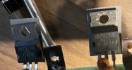
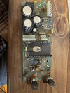
So I searched the net and found the service manual (No luck on a replacement PSU though). It states that the fuses will blow if either of the Voltage regulators are faulty as Each regulator is on the 15V and 24V path. As both fuses are popping, I'm wondering if both regulators are faulty. I'm fairly novice at all this but I do have a basic grasp of electronics and as the desk is old (And left behind by an old friend who no longer wants it) I feel like I've nothing much to lose in having a go at fixing the PSU. In the picture you can see both regulators and I've found out that they are old Fairchild parts, I am in the dark as to how I find a modern equivalent. If I could swap them out with new ones, then at least I could eliminate them from enquiries...I've got no problems in the soldering side as I am always building Modular synth parts from kits etc, it's just wehn something goes wrong, I'm still learning about how to diagnose...I'd love to learn more though!
Thanks
Pete
 

Attachments

  • Vr.jpg
    Vr.jpg
    735.2 KB · Views: 249
Nothing difficult about those, they are simple 15V regulators, the 7815 is +ve, and the 7915 is -ve, they are standard components and don't need to be Fairchild.

I wouldn't normally consider either to be most likely to blow fuses, the bridge rectifier BR22 is more likely, and is easily checked using a meter on the diode test range. However, if that checks OK, then there is a chance of the regulators blowing fuses, as there's a crowbar circuit (C106D and MC3423) on the output of the regulators, this is designed to blow the fuses if the regulators fail, to protect the rest of the mixer.

I presume CN3 at the right hand side is a plug/socket and can be simply unplugged? - this would allow you to work on it with no danger to the rest of the mixer
 
That's a speedy reply! thanks for this...Having a look at eh service manual, it does mentions the Crowbar system, using 'an MC3424 IC and a C106D thyristor. If the voltage across the +/- Volt rails rises above approx 32V the Thyristor will operate and short the rails together thus causing the regulators to current limit. Should a regulator fail, the low voltage fuses will blow.'
Looking t the board, you almost have seen it reading your reply! I know I've come to the right place for help! (Thank you thank you!)
Now I can see the IC and the 106 component, but I still need a bit of help understanding the basics of what it all means..
So...If I attach a picture of the board, is the BR22 obvious? Is it the square part near the large Capacitors?How should I go about testing it? I've got a meter but till now, I've normally used it to check resistor values and checking cables work...Any help is greatly appreciated as forums like this are so helpful to me ...web pages etc normally assume some prior knowledge if you know what I mean..
Thanks
Pete
 

Attachments

  • Seck PSU board.jpg
    Seck PSU board.jpg
    1.1 MB · Views: 232
BR22 is a bridge rectifier, and the fuses connect to it, it's the square component at the top, above the capacitors in your last picture. It's essentially four diodes in one unit, so you test it like four diodes.

 
That's so helpful...I know I said I've no real idea about all this but how you knew all the parts of a PSU you hadn't seen is pretty darn good!
So in order to test these parts, how should I go about it? I read that in order to test I need to put the +ve lead from my multimeter (Diode mode) to the -Ve on the rectifier. then touch the AC legs...one gives me a reading of 0.6, the other AC leg gives nothing. When I switch and put the Multimeter -ve, to the +ve on the rectifier, I get 0.6 on both ac legs...does this mean it's faulty, I mean, should I get the 0.6 from both ways round? Also, the print on it's side says BR32...is this the reference I should use if I need to order a part?
I'm loving the hunt for a solution!
 
I know the power supply because I downloaded the manual, which you mentioned was available. It's a pretty standard and simple power supply, with the slight complication of the crowbar circuit.

A diode should read 0.6V or so one way round, and high the other - if any of the diodes was faulty it would read lower than that both ways round. Where the two pins read 'nothing' does that mean it reads the same as if you touch the meter probes together?, if so that diode is short circuit and you need to replace the bridge rectifier.

The BR32 is easily available:


But rectifiers generally aren't critical, and any 3A 200V bridge rectifier would be fine, as long as the connections were the same way round (they do vary a little). But if you're ordering one, you ay as well order a BR32.
 
This is very helpful indeed… I’ll confirm the meter reading in the morning but I’ll also order another br32 as well… in the meantime thank you and I’ll shall see how it looks tomorrow..
 
I had it in storage for a few years and recently got it out to start using it once more and when plugging it in, the fuse pops...there are 2X2A quick blows.
This tells me that a component has failed while sitting in storage. Solid state components like rectifiers and voltage regulators rarely fail just from sitting. The component most likely to fail while in storage is the electrolytic capacitor. I'd be suspicious of the electrolytic capacitors in the power supply. Considering that they're inexpensive, I'd probably just replace them all and be done with it.
 
This tells me that a component has failed while sitting in storage. Solid state components like rectifiers and voltage regulators rarely fail just from sitting. The component most likely to fail while in storage is the electrolytic capacitor. I'd be suspicious of the electrolytic capacitors in the power supply. Considering that they're inexpensive, I'd probably just replace them all and be done with it.

As it's not switch-mode it's rarely a problem, and the caps look visually good - and as it sounds like the bridge is S/C then that should cure the fault.
 
All of this is duly noted...I have taken the decision to get various components as a safety...I've ordered the Bridge from Mouser and also all the Capacitors, as well as the regulators. I'll start with the Bridge first when they all arrive and test it from there...hopefully it'll just be the bridge but I guess it doesn't hurt to have the other bits to hand.
I noticed when testing the Bridge...So I put the positive of the meter to the negative of the bridge and all the other pins read: 0.6
When I swap and put the negative of the meter to the positive of the bridge I get 0.6 on all pins bar on of the AC pins which reads zero...does this sound like a faulty bridge?
Can't help thinking that if I get to the bottom of this (with some very appreciated help) then this may well open the door for me to get very into this side of electronics....I have a very old Sequential circuits synth programmer I'd like to have a go at too!
Pete
 
Until the bits arrive, I can't really do a whole lot. I got them from Mouser, I'm not sure how long things take to get delivered from them but once they are here, I'll start with the bridge and report back...
Cheers
Pete
 
Do you mean the first or the second? Have you clicked on them and zoomed in...bit tricky to get a better first one with the rubbish iphone though
 
If the voltage across the +/- Volt rails rises above approx 32V the Thyristor will operate and short the rails together thus causing the regulators to current limit.
unsolder the leads to the thyristor and bend them out of the board, then see if it continues to blow fuses. i have a collection of old analog open-frame power supplies that had a similar crowbar circuit in all of them., and got them all because they blew fuses, and the company i worked for was more likely to replace them and throw them out than try to fix them. in every case, the thyristor was shorted, and that's what was blowing the fuses.
 
Is that the three legged component in the centre of the board screwed to the heat sink? Is there a way to test it before unsoldering it, or can it not be reliably tested whilst on the board?
Thanks
Pete
 
Well, the bits have arrived…..the bridge, regulators and capacitors.. when I get a chance (flippin work…honestly!) I will change each then test to see what’s what.. I’ll report back as and when..
Thanks
Pete
 
Hello all,
I finally had the chance to sit down and do some soldering… I decided to replace parts one at a time, then reassemble and test to see if the fuses blow…
I first swapped out the bridge rectifier…
Pop…
Ok, so I then swapped out the larger electrolytic capacitors….
Pop…
At this point I was eating up fuses so I thought I’d swap out the regulators.. the 7815/7915 regulators…
Pop…
Hmmm aside from the ceramic capacitors (which I’ve got a bunch of) the only big bit to replace is the 106 in the middle screwed down… I’m wondering if I should get one of those and replace that.. kind of miffed that I didn’t get any of them when I ordered the rest from mouser, I only need one! Plus I’m unsure about how to source one that’s the same dimensions, also, with the metal plate so it can be screwed down or is that not as important?
Thanks
Pete
 
As I explained earlier, the BT106 is a crowbar circuit, designed to blow the fuse and to do nothing else. Take it out and test the PSU without it - but DON'T PLUG THE REST OF THE MIXER IN TO THE PSU - just power in to the PSU, and nothing else connected.

Assuming it doesn't blow the fuse?, then measure the output voltages which should be +15V and -15V. Assuming they are OK?, either the BT106 is faulty, or the IC feeding it.
 
Status
Not open for further replies.

Latest threads

New Articles From Microcontroller Tips

Back
Top