Continue to Site

Welcome to our site!

Electro Tech is an online community (with over 170,000 members) who enjoy talking about and building electronic circuits, projects and gadgets. To participate you need to register. Registration is free. Click here to register now.

  • Welcome to our site! Electro Tech is an online community (with over 170,000 members) who enjoy talking about and building electronic circuits, projects and gadgets. To participate you need to register. Registration is free. Click here to register now.

Help how does this current transducer work

Status
Not open for further replies.
Hello ,

Thanks for the drawing. I'll try it. But I'm still confuse does the supply voltage different from the load? and does a current transducer different from a current transformer? they seems to have the same function but a different supply voltage.

Thanks.
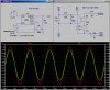
Check this drawing...
 
Strictly speaking, a current transformer DOES NOT require any external supply to produce an output signal...the transformer effect will couple a replica of the input current scaled down by the turns ratio. All that is required is a burden resistor on its output to produce an useful voltage signal.

On the other hand a current transducer, whether hall effect or magnetorestrictive, requires a power supply for the amplifying and conditioning circuitry, since the output signal from those devices is too low to be useful.
The added circuitry makes them costlier.
The advantage is that you can sense current all the way to DC, whereas a current transformer has a minimum operating frequency (known as the E*t product).
 
Hello ,

Thanks for the drawing. I'll try it. But I'm still confuse does the supply voltage different from the load? and does a current transducer different from a current transformer? they seems to have the same function but a different supply voltage.

Thanks.

Hello again,

The supply voltage supplies power to the current transducer. That's all that it does. You may have another supply voltage that runs the load however, and in some cases you may be able to use that for the power to the transducer, but it has to be the right voltage and it has to be a split supply or you have to be able to make it a split supply of the right amplitudes. In other words, you need a plus and minus power supply to power the transducer, and perhaps that supply also powers the load. The power supplies should be stable though.
Note again that there are two voltage required possibly three:
1. The positive transducer supply
2. The negative transducer supply
3. The supply that powers the load.

The transducer supply voltages do not have to provide too much current however, just maybe 100ma each.

The current transformer is just a passive device that needs no electrical power input, while a current transducer does when it contains electronic parts like amplifiers (normally a Hall Effect Sensor combined with a chopper stabilized amplifier).
 

Attachments

  • LEM HX 50-PSP2.asc
    967 bytes · Views: 246
  • LEM HX-50.asy
    841 bytes · Views: 267
  • Sticky Notes.txt
    180 bytes · Views: 241
It is a hall-effect current transducer so that the output circuit (pins 1 to 4) are isolated from the sensing pins 5 and 6), but I think you have to cut the wire that it senses, and connect the cut ends to pin 5 and 6, respectively.

What a stupid data sheet. It says almost nothing.
 
Last edited:
Here is a hack at it:
 

Attachments

  • HX50.jpg
    HX50.jpg
    369.3 KB · Views: 299
  • HX50.asc
    1.5 KB · Views: 241
  • HX50.asy
    489 bytes · Views: 245
  • HX50test.asc
    1 KB · Views: 252
I have been trying to create a model the has current input and it seems to me the the H parameter is what I want to use.
H. Current Dependent Voltage Source
Symbol Name: H
Syntax: Hxxx n+ n- <Vnam> <transresistance>
This circuit element applies a voltage between nodes n+ and n-. The voltage applied is equal to the value of the transresistance times the current through the voltage source <Vnam>.
Syntax: Hxxx n+ n- value={<expression>}
This is an alternative syntax of the behavioral source, arbitrary behavioral voltage source, B.
Syntax: Hxxx n+ n- POLY(<N>) <V1 V2 ... V3> <c0 c1 c2 c3 c4 ...>
This is an archaic means of arbitrary behavioral modeling with a polynomial.
.
I just don't know how to use this information to create the .sub, .lib, or whatever it needs to support the .asy
As I understand it, we put a symbol in the schematic, and it links to a .sub or .lib and the .sub or .lib has the operational instructions for that symbol.
So I'm asking for help in creating or completing the HX-50.LIB or text.
Thank you,
Kinarfi
 

Attachments

  • LEM HX 50-PSP2.asc
    967 bytes · Views: 233
  • HX-50.asy
    491 bytes · Views: 221
  • HX-50.txt
    233 bytes · Views: 234
Or you can just use a hierarchical schematic like I used. LTSpice has the ability to define what would otherwise be a .SUB using their graphics editor instead of a text editor. I created the schematic model of the HX50 directly from the data sheet. I put I/O ports on it. I then let LTSpice create the symbol automatically. I massaged it to make it more user friendly. I then placed that new symbol in the test circuit.

If you insist on having a .txt or.sub text file instead of using the hierarchical schematic, then save the netlist that is created during a SIM run using my example, and extract the .SUB from that.

Since one of the salient properties of the HX50 is its frequency response, it is much more natural to use the voltage-controlled voltage source I used in my model. That allowed me to model the low-pass frequency response by placing the RC between the current sampling resistor and the VCVS.

Even though the HX50 uses a Hall-Effect sensor, I'll bet that the internal resistance of the traces inside the package are higher than the 1 milliOhm I used to convert current to voltage.
 
Last edited:
Thanks Mike, still working on your suggestions, but the HX50 s don't seem to give the desired results, that is at 0 current, out should be 2.5v and at 50 amps out should be 3.125v. chech the picture
 

Attachments

  • HX50TEST-J.png
    HX50TEST-J.png
    59.1 KB · Views: 295
Trying use h.asy and it says,
Linear Current-Controlled Voltage Sources
General form:
HXXXXXXX N+ N- VNAM VALUE


Examples:
HX 5 17 VZ 0.5K
N+ and N- are the positive and negative nodes, respectively. VNAM is the name of a voltage source through which the controlling current flows. The direction of positive controlling current flow is from the positive node, through the source, to the negative node of VNAM. VALUE is the transresistance (in ohms).

Where & how do I use this? Especially, where do n+ and n- go? I have always had a respect for those who teach and if I learn this, I can apply it to other items in spice.
Thank you and I appreciate any help.
Kinarfi
 

Attachments

  • HXJ-50.asc
    900 bytes · Views: 241
  • h.asy
    431 bytes · Views: 244
Two methods. Take a guess which one I prefer. The two plots of V(hout) and V(bvout) align align perfectly. I didn't have to create any symbols; I used only the ones provided.
 

Attachments

  • Draft96.asc
    1.7 KB · Views: 234
Last edited:
Thank you, thank you, works great.
 
Thank you, thank you, works great.
The hierarchical model I uploaded previously works even better, because it accounts for the frequency response...
 
Any symbol I have made from a workable schematic using the hierarchy function always fails and usually says it can't find the schematic, see "still not working .png
I keep thinking I'm working with dc, but then I remember I have a 20KHz oscillator. If you want to see where I using the LEM HX50, it's in the 2013-10-06 POWER STEERING Looks Great - next.asc.
It's not quite done yet, the output of the LEM will trip the relay when the motor reaches it's end of travel and replacing the output of the Hall, which is responsive to steering wheel torque, with the nuetral voltage of 5v, now I need to hold the relay in until the torque is back to 0.
Thanks Mike, you've been a wonderful help.
Kinarfi
 

Attachments

  • LEM_HX_50 hier.asy
    340 bytes · Views: 218
  • LEM_HX_50 hier.asc
    972 bytes · Views: 260
  • Draft1.asc
    651 bytes · Views: 273
  • STILL NOT WORKING.png
    STILL NOT WORKING.png
    207.8 KB · Views: 264
  • 2013-10-06 POWER STEERING Looks Great - next.asc
    18 KB · Views: 271
Status
Not open for further replies.

New Articles From Microcontroller Tips

Back
Top