Continue to Site

Welcome to our site!

Electro Tech is an online community (with over 170,000 members) who enjoy talking about and building electronic circuits, projects and gadgets. To participate you need to register. Registration is free. Click here to register now.

  • Welcome to our site! Electro Tech is an online community (with over 170,000 members) who enjoy talking about and building electronic circuits, projects and gadgets. To participate you need to register. Registration is free. Click here to register now.

Help for Newbie.

Status
Not open for further replies.

sandoza

New Member
Hi to all of members.

This is my first post to this forum. I am new to the field of electronics.Just took couple of weeks to understand electronics building by building small and simple transistor based projects.The only knowledge i previously have is how to make a pcb at home from given layout, never tried to design my own.Thought not having enough knowledge of electronics. So as with passage of time my knowledge of electronics is increasing, I am in my way to take some projects based on OP-AMP's. And just got free version of EAGLE layout CAD program to try my first Pcb.

As for know i need an adjustable lab power supply. i think not to waste money on batteries i had been using during all the time.
And even i have to still stuck to batteries, the rechargeable ones are an obvious choice.

Now the problem. If i stick to rechargeable batteries, i need a laboratory power supply to recharge them.Different types of batteries require different voltage and current to recharge them safely.

I can make a simple power supply with LM317. And for OP-AMP a dual power supply may be needed so LM337. But if i make these,the different batteries require to be charged at different current, So Lab power supply is must.And when i would progress in electronics field i am obviously going to need one.

I already tried some so called famous designs for lab power supplies, from famous websites, but some partially worked other's did not at all.

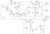
Now i need your help to design one lab psu. The last circuit i tried and build on a breadboard did not worked, the power supply did not respond at all to potentiometers.The output voltage remained same all time.I rechecked the breadboard connections four times and found no mistake,but it did not work.

I am attaching here the schematic of the said lab psu. lets see you people can help me by mentioning any defects in schematics and their solution.Please!
(Sorry for long post, i thought i should mention the background of myself and my problem so you people could take it with better attention).

Thank you very much.
 

Attachments

  • ed.JPG
    ed.JPG
    327.9 KB · Views: 182
I wonder if you could provide a reference for where you got your schematic?

One thing that struck me is your tapped transformer voltages. I'm seeing 20 V before your rectifier, then after the rectifier I see a 15 volt regulator.

Is the voltage printed on the transformer secondary indicitive of peak-to-peak AC? If that is the case, you will be getting less than 10 volts out of your rectifier and not enough to regulate at 15 volts. I would not expect to see a voltage printed on a schematic at a particular "test point" that isn't the value you would find. At the secondary there, you would be reading AC, voltage stepped down. There is no logical reason to print the half wave voltage at a point where it isn't read.

I am not sure if your fault condition reflects this observation, and it may very well be a non-standard representation on the schematic and meaningless. HOWEVER, if your schematic did not include a parts list, and you followed the meaning here verbatim, I wonder if you selected an inadequate transformer.
 
Here is the link to the website where i found the schematics.www.Hobby-Electronics.info - Electronics Course
Although the project is explained in details by the author.Yet being less experienced in electronics i just followed the explanation.The only thing i changed is that i am using separate transformers one with 30v secondary and other with 20v secondary.The author says its OK to use separate transformers.I did not changed anything else not even a single resistor value.

Please have a look at the project and give me some help. And if this project is absolutely not workable, Please let me know the website where i can find a really working lab psu or if anyone can give me a schematics of well working unit on this forum, will please me more than enough.

I can buy lab psu from many vendors but the happiness when as hobbyist you get some thing working by yourself will be pretty much gone.
Thank you very much.
 
That's an extremely overcomplicated and old fashioned power supply.

I would look for a simple "variable power supply" using a LM317, they only have a few parts and the LM317 also has internal current limiting at about 1.5 amps which saves parts there.

If you want selectable current limiting you can add a second LM317 as a current regulator before the main LM317 voltage regulator.

This one looks about right;
LM317 VARIABLE POWER SUPPLY

And don't forget 2 of the most important features for a experimanter's PSU; a voltmeter and ammeter. My preference is for analog meters, it's VERY handy being able to watch the needles move up and down as things happen in your circuit.
 
Using two LM317, one for current and one for voltage may not result in very good and stable power supply. There must be some better ideas.I am still waiting with passion to see them emerging from super brains on this forum.
 
Here is the link to the website where i found the schematics.www.Hobby-Electronics.info - Electronics Course
Although the project is explained in details by the author.Yet being less experienced in electronics i just followed the explanation.The only thing i changed is that i am using separate transformers one with 30v secondary and other with 20v secondary.The author says its OK to use separate transformers.I did not changed anything else not even a single resistor value.

Please have a look at the project and give me some help. And if this project is absolutely not workable, Please let me know the website where i can find a really working lab psu or if anyone can give me a schematics of well working unit on this forum, will please me more than enough.

I can buy lab psu from many vendors but the happiness when as hobbyist you get some thing working by yourself will be pretty much gone.
Thank you very much.


If you have purchased all the components for this supply, I would not give up on building it. Even if it is complicated.

I am still "stuck" on the transformer being a possible issue. (Note that I may be overlooking a key item here, so hopefully someone will come along and correct any incorrect thoughts on my part)....

An LM7815 requires a minimum of 17.7 volts at the input terminal to maintain regulation.

So lets step through the initial circuit to the 15 V regulator. The output of the transformer says 20 V. OK fine then. Is that RMS value or half wave voltage? You would expect the AC RMS value, the voltage OUT at that point, to be what is printed there, no? The next step in the circuit is the B40C800 bridge rectifier. The datasheet for it says that the forward voltage drop per diode is 1 volt if I read it correctly, so you are rectifying the voltage, which is 20 VAC RMS, then rectified you have 10 VAC, minus the bridge voltage drop which appears to be 2 volts. You you are presenting 8 volts to a 15 volt regulator? That won't work.

Perhaps the gentleman who drew this meant the secondary after rectification would be 20V DC. That makes more sense, because the datasheet for the rectifier expects 40 volts RMS at the input. This would mean 20 Volts out minus the voltage drop, which would be 18 VDC, which is just above the regulator's minimum input voltage and would be an efficient scheme.

I am a repair guy, so I don't often replace transformers. They usually don't fail, but I would not ordinarily think transformer secondaries are rated for rectified voltages. That doesn't make sense, transformers are used for other things besides DC power supplies and this would create ambiguity. And my experience has never been to see this.

So, I believe there is a confusing ambiguity in this schematic.
Question, do you still have the transformer? You should disconnect it from the output circuit and connect your AC voltmeter leads to the "20V" secondary. Apply mains power. What do you read? If you are reading 20 volts, your transfomer is not adequate for the task, in my opinion. If you have 40 volts, then there is another problem.

And if the ambiguity is consistant, the 30 V secondary might be 60 volts instead. The circuit is a little less obvious at this point, but I can only conclude that both of your transformers are incorrect if you are measuring what is printed on the schematic.

I would attempt to contact the designer and clear this up.
 
Last edited:
Ok here are the results of transformers i am using, with a good digital multimeter.

The 30V transformer.
AC voltage=31.9v
DC without capacitor=27.9V
Dc with capacitor=41.6V.


The 20v transformer.
AC voltage=28v
DC without capacitor=24.8V
DC with 470uf capacitor=38.3V.

And yes i bought all components new from vendor except 30v transformer which i already had.
 
OK, I'll admit not being the sharpest knife in the drawer.

But first, how can the RMS AC voltage be rectified with only 3 volts lost? That makes no sense to me. OK, the capacitor is there before the regulator, and I can see an increase in voltage coming from a capacitor but I would have expected that for smoothing and not increasing voltage. Maybe someone else can offer an explanation.

At any rate, depending on the exact 15 V regulator you are using, 38.3 V exceeds the absolute maximum rated input for the LM7815, and typical inputs range from 17.5 to 30 volts. So in this case you may be overdriving that regulator.

I'm still not clear on how your values are occuring.
 
I can not explain the voltage drop part. But as far as the increase in voltage at capacitor is concerned, it always happens to me at least unless there is some load is connected.With small load the voltage drops back to original rectified voltage.

While taking the measurement i did not touch any wires, my multimeter came with optional prongs those can hook on twisted ends of wires.

May be we should wait for anyone more experienced to see the posts and discuss.
 
Ok here are the results of transformers i am using, with a good digital multimeter.

The 30V transformer.
AC voltage=31.9v
DC without capacitor=27.9V
Dc with capacitor=41.6V.


The 20v transformer.
AC voltage=28v
DC without capacitor=24.8V
DC with 470uf capacitor=38.3V.

And yes i bought all components new from vendor except 30v transformer which i already had.

Please answer a question.

When you are measuring the DC voltage "with" capacitor and "without", where are you placing the ground lead of your digital multimeter?
 
As i told in previous post my multimeter came with optional prongs those can hook on to twisted ends of wires.
 
One thing i must mention is that i am from Pakistan and its common practice here in household wirings, that they don,t use common ground, i mean we have 2-phase 220v wiring and plugs/sockets are two pin only.Only industrial wirings are 3-phase and heavy duty industrial plugs and sockets are 3-pin.Why? i dont know.
 
As i told in previous post my multimeter came with optional prongs those can hook on to twisted ends of wires.

Yes, but this does not tell me where you are placing the ground lead of the voltmeter with each measurement.

For instance, are you placing the ground lead on the secondary winding output, and taking all DC measurements from this ground reference? When you measure voltage after the bridge rectifier, are you directly measuring voltage from rectifier (-) to rectifier (+)? Or from another ground point?

For me to make sense of this it is important that your measurements are taken from proper locations on the circuit.

In fact, I notice there are multiple test points labeled ground at different potentials on the schematic. It is important to take direct measurements. Be careful with the voltages at the transformer, I am not from Europe or Asia so I am not familiar with your mains voltages. I have a feeling you do not have a neutral point from which ground reference is made.
 
Last edited:
Ke5frf,
The output of a power transformer is measured in volts RMS.
The 30V transformer is pretty good because its voltage does not go too high when it does not have a load (the 20V transformer is horrible because its voltage is 28V without a load).

When the transformer output is full-wave rectified and filtered with a capacitor then the capacitor charges to the peak voltage of the AC minus the rectifier voltage drop.
The peak voltage is 1.414 (the root of two) times the RMS voltage. A full-wave bridge rectifier has a voltage drop of 1.4V without a load and 2V with a few amps of current.

So the 30V transformer measured 31.9V RMS without a load. Its peak voltage is 45.1V and the rectifier drops the filtered voltage to +43.7V. He measured 41.6V which is close.
 
Last edited:
Yes i do not have the ground reference. So all reading for AC voltages are taken directly by placing prongs at the secondary wires. And DC voltage is measured from +& - of bridge rectifier.
 
Using two LM317, one for current and one for voltage may not result in very good and stable power supply. There must be some better ideas.I am still waiting with passion to see them emerging from super brains on this forum.

Son, you just dishonored one of the sharpest minds on this, or any other, forum.
 
Ke5frf,
the output of a powwer transformer is measured in volts RMS.
The 30V transformer is pretty good because its voltage does not go too high when it does not have a load (the 20V transformer is horrible because its voltage is 28V without a load).

when the transformer output is full-wave rectified and filtered with a capacitor then the capacitor charges to the peak voltage of the aC minus the rectifier voltage drop.
The peak voltage is 1.414 (the root of two) times the RMS voltage. A fulll-wave bridge rectifier has a voltage drop of 1.4V without a load and 2V with a few amps of current.

So the 30V transformer measured 31.9V RMS without a load. Its peak voltage is 45.1V and the rectifier drops the filtered voltage to +43.7V. He measured 41.6V which is close.

Yes, yes, yes. Doh!!! Dumb dumb dumb me for forgetting to account for RMS vs. peak voltage. That is as basic as it gets.

What irks me is that this is something I've forgotten more than once :)

Well, it just goes to show how easy it is to forget such details, especially when your troubleshooting over a computer.
Thanks Audioguru for setting the record straight.
 
From audioguru's post seems that he is also having the same view for faulty 20v transformer. I think i should buy a knew one from different manufacturer.And see what happens.But its going to take few days.
 
From audioguru's post seems that he is also having the same view for faulty 20v transformer. I think i should buy a knew one from different manufacturer.And see what happens.But its going to take few days.

Before you do that, I think this long post could have been avoided by asking you to measure voltage after the regulator. If it is right at 15 volts it should not be an issue anyway as long as it doesn't intermittently get hot and "drop out".

I apologize for the long posts overlooking such a critical detail. I pride myself on being helpful and sharing knowledge but my brain is like a computer with a virus sometimes and "files get corrupted" LOL. :mad: mad at myself!
 
Status
Not open for further replies.

Latest threads

New Articles From Microcontroller Tips

Back
Top