Continue to Site

Welcome to our site!

Electro Tech is an online community (with over 170,000 members) who enjoy talking about and building electronic circuits, projects and gadgets. To participate you need to register. Registration is free. Click here to register now.

  • Welcome to our site! Electro Tech is an online community (with over 170,000 members) who enjoy talking about and building electronic circuits, projects and gadgets. To participate you need to register. Registration is free. Click here to register now.

Help:Digitally controlled current source

Status
Not open for further replies.
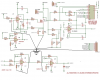
I can't follow your layout, but the biggest potential problem with ground is the current through R4 and R5, which can be, IIRC, one Amp max. This current needs to return directly to the +12V supply without passing through any traces that go to amplifiers or resistors which are in the signal path. The term for this sort of system is "star ground", where all grounds return to a common point on the board, without any branches.
I will try to draw a schematic which shows this, but I'm on the road back home right now, so I may not get it done.
 
Here is an example. I would use a ground plane for power supply ground, and return all decoupling caps and logic grounds to the ground plane. The power supply ground wires should connect as closely as possible to the star ground point, which is a point on the grounf plane. All the grounded wires shown should go to that star point, instead of going directly to the ground plane. This prevents ground currents from interacting by creating microvolt or millivolt drops across parasitic ground resistances.
 

Attachments

  • Abicash's schematic with star ground.PNG
    Abicash's schematic with star ground.PNG
    296.7 KB · Views: 243
:) thank you so much for the interest you showing even when on a road trip.
I have more or less used the same method to connect grounds to a common ground.
I think i have to live with this :(
 
Hello Ron

I am having oscillations VDIFF as seen here.Maybe thats the root cause of all the errors.
Can you comment?

7-4247333962_f9bb892682_o.png
 
Last edited:
I'm guessing your current sink is oscillating, but it's hard to say for sure. Use your troubleshooting skills and trace the oscillation back to its source.
 
Last edited:
I am sure the current sink is oscillating.I tried adding a RC feedback to the sink opamp to no avail.
These kind of sinks work on error correction and i feel that the correction rate may break into oscillations.Or no?
Anyways i have added a filter at VDIFF which smooths the sinewave to dc..Is this correct?
The oscillations may cause your current sink output to be an unpredictable function of the input (DAC) voltage. A filter will get rid of the oscillations, but the current may not be what you predicted.
I simulated the circuit with LTspice, and it was stable. Unfortunately, simulations do not always reflect reality. They are limited by the accuracy of the models, and by their inability to anticipate parasitic reactances and resistances in the actual hardware.
 
But you think that this current sink should NOT oscillate at all?
That's correct. Do you have power supply decoupling caps on each op amp, with short leads, from each power pin to GND? I don't see them in your schematic. Op amps can and will oscillate without them.
 
Last edited:
Hi Ron

I have re-checked the whole thing and found out that the current sink isn't oscillating.:eek:

The differential amplifier is the oscillating section.I removed the mux to see if it's the source of errors,but it is not one.
I tried adding capacitors across (and in series) with the feedback resistors but the oscillations occur at reduced frequency ,but are still present.
You have any ideas

Thanks and regards
 
Last edited:
Hi Ron :)

Since i figured that the Diff.Amp was oscillating , I tried a lot of things to reduce the oscillating freq.But i never got a DC signal there.The freq did reduce though.Adding an RC at the o/p of that made matters worse.
So i replaced this (7650) op-amp by an OP07...and voila...the oscillations are gone :D
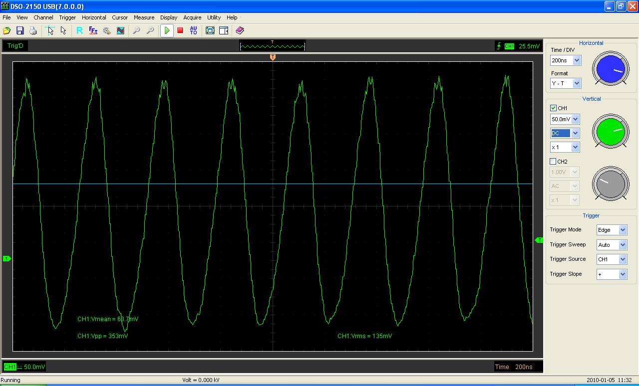
..i get a fairly good DC voltage here,which can be read by the ADC and reproduced by a DAC.
There are of course intrinsic offsets which i cannot think about how to remove ,at the moment.But it is now going in a good direction.
I also got the adder to work and the later amplification stage (doesn't work with A=300,works with A=200 & 100)
I will get a new board designed with all the analog and digital parts on a single board taking into consideration the Ground planes you mentioned.

Thanks and regards
 
Try adding a small cap (100pF?) from the output to the inverting input of the diff amp.
 
You may still have oscillations. I think they may be due to the capacitance on the inverting input of the difference amp. The capacitance is from the CD4053, and parasitic capacitance of the wiring between the 4053 and the amp. A cap across the feedback resistor is generally the way you compensate for this.
 
I have already included that.Although it did not make any difference.The oscillations had vanished when an OP07 replaced 7650.The VDIFF doesnt replicate voltage across the load.Some mv error is present.Maybe critical board design may take care of that.
 
Hi Ron :)

Last week i got a new board designed with all the recommendations and tested it by simulating all the conditions and it worked fine.
I then checked the current sink,and it still was oscillating.I tried a lot but could get the oscillations removed.So i replaced the MOSFET by a TIP122 and adjusting biasing resistors.Still no go.
So i removed the Load from the high side and put it below the Transistor (just above the sense resistors) and juggling a bit,i got it working eventually!!!!
Now perfect replication of Current-set --> Load --> VDIFF -->Dac-ref-set-->VCAL-->Vsample
I am very happy :D

Thanks and regards
Excellent!:)
 
Status
Not open for further replies.

Latest threads

New Articles From Microcontroller Tips

Back
Top