Recently I bought 1 PNA4601 IR receiver as well as 1 IR transmitter.
When I plug the IR transmitter and receiver onto Basic Stamp microcon and use the FreqOut command at 38500KHz, it works perfectly.. But them when I tried to construct a 555 timer circuit to send 38KHz through the IR transmitter, the PNA4601 receiver just cannot seem to detect the IR. I even put the transmitter soo close until both of the transmitter and receiver kissed each other and yet it doesn't want to work..
I have tried 2 different circuits with different components value for the 555 timer and both failed to work.
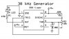
The first circuit I tried is found in IR_555Timer1.jpg attached below..
When I connect the output to the oscilloscope, it shows something like 70% duty cycle instead of 50%.
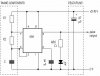
The second circuit I tried ia IR_555Timer2.jpg. The values for R1, R2 and C are 1K, 18K and 1nF respectively.. This time, when I connect the output to oscilloscope, it shows a 50% duty cycle. I even adjust the frequency to 38.5KHz with the potentiometer but it still refuse to work.
I have run out of ideas on how to make the IR work and am in desperate need of some help.. I have supplied continuous pulse of 38Khz and nothing seems to work.. Can somebody please help me..?
The purpose of the IR is for obstacle avoidance..
Thanks a million..
When I plug the IR transmitter and receiver onto Basic Stamp microcon and use the FreqOut command at 38500KHz, it works perfectly.. But them when I tried to construct a 555 timer circuit to send 38KHz through the IR transmitter, the PNA4601 receiver just cannot seem to detect the IR. I even put the transmitter soo close until both of the transmitter and receiver kissed each other and yet it doesn't want to work..
I have tried 2 different circuits with different components value for the 555 timer and both failed to work.
The first circuit I tried is found in IR_555Timer1.jpg attached below..
When I connect the output to the oscilloscope, it shows something like 70% duty cycle instead of 50%.
The second circuit I tried ia IR_555Timer2.jpg. The values for R1, R2 and C are 1K, 18K and 1nF respectively.. This time, when I connect the output to oscilloscope, it shows a 50% duty cycle. I even adjust the frequency to 38.5KHz with the potentiometer but it still refuse to work.
I have run out of ideas on how to make the IR work and am in desperate need of some help.. I have supplied continuous pulse of 38Khz and nothing seems to work.. Can somebody please help me..?
The purpose of the IR is for obstacle avoidance..
Thanks a million..
Attachments
Last edited: