Continue to Site

Welcome to our site!

Electro Tech is an online community (with over 170,000 members) who enjoy talking about and building electronic circuits, projects and gadgets. To participate you need to register. Registration is free. Click here to register now.

  • Welcome to our site! Electro Tech is an online community (with over 170,000 members) who enjoy talking about and building electronic circuits, projects and gadgets. To participate you need to register. Registration is free. Click here to register now.

Help Designing an Ignition Coil Tester

Status
Not open for further replies.

milkoni

Member
Hi,
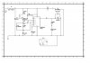
I would like to build a circuit with 555 timer, for testing spark of car ignition coils. I've built the timer circuit, but I have difficulties to choice a proper transistor.
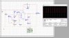
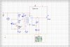
I've attached my circuit. The resistance of ignition coil is approximately 5 Ohms. I'm not sure, but I think that the amperage is about 2-3 A.

Thanks in advance!
 

Attachments

  • coil_spark_tester.jpg
    coil_spark_tester.jpg
    208.1 KB · Views: 1,651
An IRF640 would be a Better Mosfet.
And it Requires a Heat Sink, to help keep it Cool.

The Diode you put Across the Coil should NOT be included.
As it is Not used on a Coil in a Car and it will Supress the Spark.
 
An IRF640 would be a Better Mosfet.
And it Requires a Heat Sink, to help keep it Cool.

The Diode you put Across the Coil should NOT be included.
As it is Not used on a Coil in a Car and it will Supress the Spark.
Thank you very much!
 
On an ignition points system:
https://en.wikipedia.org/wiki/Ignition_system

The ignition firing sequence begins with the points (or contact breaker) closed. A steady current flows from the battery, through the current-limiting resistor, through the primary coil, through the closed breaker points and finally back to the battery. This current produces a magnetic field within the coil's core. This magnetic field forms the energy reservoir that will be used to drive the ignition spark.

As the engine turns, the cam inside the distributor rotates. The points ride on the cam so that as a piston reaches the top of the engine's compression cycle, the cam causes the breaker points to open. This breaks the primary winding's circuit and abruptly stops the current through the breaker points. Without the steady current through the points, the magnetic field generated in the coil immediately collapses. This severe rate of change of magnetic flux induces a high voltage in the coil's secondary windings.

At the same time, current exits the coil's primary winding and begins to charge up the capacitor (condenser) that lies across the open breaker points. This capacitor and the coil’s primary windings form an oscillating LC circuit. This LC circuit produces a damped, oscillating current which bounces energy between the capacitor’s electric field and the ignition coil’s magnetic field. The oscillating current in the coil’s primary produces an oscillating magnetic field in the coil. This extends the high voltage pulse at the output of the secondary windings. This continues beyond the time of the initial field collapse pulse. The oscillation continues until the circuit’s energy is consumed.

The MOSFET does the same thing as the breaker points. I got a much better spark with an automotive condenser / capacitor between the negative coil terminal and ground.

Primary ignition.jpg

This is the primary side.

Points secondary.jpg

Secondary pattern.
 
Last edited:
Thank you ClydeCrashKop
I forgot to say that I mean an electronically controlled coil - one coil for each spark plug, placed on top of the spark plug (coil-on-plug or Direct Ignition).
The test process is:
  • Ensure the ignition off.
  • Disconnect ignition coil multi-plug.
  • Remove ignition coil.
  • Connect test spark plug to ignition coil.
  • Reconnect ignition coil multi-plug.
  • Connect wire between spark plug threads and suitable earth.
  • Briefly crank engine.
  • Check for strong blue spark.
  • Repeat test for other ignition coils.

NOTE: Disconnect injector multi-plugs, before cranking tests, to avoid damage to catalytic converter(s).

With my circuit I would like to perform this test without disconnecting injector multi-plugs and without crank the engine. I saw that my previous circuit is totally wrong. The pulse for inductance is very short and disconnection pulse is long. It's necessary the pulse for inductance to be long, and disconnection pulse to be short.
 

Attachments

  • coil_spark.jpg
    coil_spark.jpg
    20.2 KB · Views: 569
  • coil_spark_tester.jpg
    coil_spark_tester.jpg
    169 KB · Views: 811
Your MOSFET circuit should work fine if you add the condenser. The MOSFET should conduct 50% of the time to charge up the coil. If you want to fine tune it, use a dwell meter set for a 4 cylinder engine and adjust the 555 duty cycle to read 49 to 55 degrees dwell.

Transistor ignition.jpg
 
Last edited:
The Diode you put Across the Coil should NOT be included.
As it is Not used on a Coil in a Car and it will Supress the Spark.

I disagree. The diode is a freewheel diode since the coil is an inductive load. It is not used in an actual car ignition circuit because they (at least older models) are not switched using solid state devices (ICs, transistors). The freewheel diode is included to prevent back EMF from damaging the FET and/or the 555 timer.

However, a 1N4148 is much too wimpy. Ideally you'd want a Schottky diode, but even a 1N4007 would be sufficient.
 
Hi Milkoni

Just a few points about your car (auto) coil tester:

(1) One of the problems with a universal coil tester is the wide range of coils fitted to the different vehicles, especially these days. The info below applies to a typical coil from a 12V Kettering inductor discharge system, the most common type fitted to car engines. You do know that with lost spark coils you need to fit a spark plug to each end of the high tension (HT) winding before testing. Also it would be more meaningful if you could measure the actual HT voltage being produced by the coil rather than just checking for a spark. A low HT voltage can give some weird engine symptoms, especially on BMW straight six engines for example.

(2) When the switching element- contact breaker or semiconductor switch- is closed the coil current can build up to destructive values so you need to add a suitable ballast resistor to limit the current to a safe value around 5A. The current varies from coil to coil and also depends if an internal ballast resistor is effectively fitted in the coil. This protects both the switching element and coil. The best bet is to have a 14.7 V supply that is current limited. But not foldback or anything too fancy which may interact with the circuit and cause problems. 14.7V is a good representation of the battery voltage of a car under normal driving conditions, when the alternator is charging the battery. On some engines the ballast resistor is shorted out during engine starting. You really need to check the coil in this mode as well as in the normal operating mode.

(3) When the switching element opens the bottom of the coil swings up from 0V to around 400V, depending on the coil, at a frequency defined by the inductance of the coil, any parasitic capacitance, and the capacitor across the switching element. Without the additional capacitor, the resonant frequency is around 100KHz and with a 150nf additional capacitance the frequency drops to around 10KHz (both frequencies from memory). At the higher frequency it may be difficult to see the spark. There is also a danger that the coil could be overvolted. The capacitor must be a high current, high temperature car type.

(4) It follows from (3) above that any switching element should have a breakdown rating of 600V and preferably, for test equipment, 800V. I noticed that the two MOSFETs mentioned only have a VDSmax of 100V and 200V respectively. Note that the data sheet VDSmax is not the end of the story and you need to take other factors into account. Hence the seemingly high VVDSmax recommendation.

(5) It is important not to exceed the dv/dt rating of the switching element or it may be damaged or turn on randomly. This is more of a concern with capacitor discharge systems though. If I remember correctly, a few turns of wire on a ferox core does the job for most semiconductors.

(6) The 1N4148 diode that you show on your schematics is a worry: they are delicate high-speed devices and should never be anywhere near the blood and thunder of the coil circuit, as Matt says

(7) You need to decide if you are going to go for a single half cycle spark, which may be difficult to see, or multiple cycle. A reverse connected diode across the switching element would give a single half cycle spark and a diode in series with the switching element would give a multicycle spark. The diode needs to be at least 10A and at least 600V. A Schottky type would be good, because of the low forward drop.

(8) If using a MOSFET as the switching element, you need to take the intrinsic substrate diode into account and you may find that a series diode as in (7) above is the best approach.

(9) Your schematic for the 555 timer seems more complicated than it need be.

(10) A bit of granny advice: it is best to always clean a coil before testing. It is not so common these days because engines are much cleaner, but as is obvious a coil can appear to be faulty due to deposits shorting out the HT.

(10) To be really thorough, you should really raise the coil temperature to around 70 deg C to ensure that it performs reliably at operating temperature. Some faulty coils are OK at 25 deg C but breakdown at the higher temperatures of the engine bay and self heating of the coil.

spec

(I have designed, developed, and trialed a road vehicle ignition system, using standard coils and Capacitor Discharge (CD))
 
Last edited:
Hi spec
Hi DerStrom8
Thank you very much for your advises and recommendations.
Spec, I would like to make this tester for a few similar models ignition coils, fitted in most models Renault - Nipondenso, Sagem and Beru. Not an universal tester. I've made some calculations and I've decided that the time to coil induction to be from 2.8 to 10.3 ms - low time of timer. Time to spark - 1 ms. high time. After your instructions my circuit looks like that now: For the timer part I think that everything is ok now. But I think that the part with ignition coil isn't proper. I need help with circuit for it.
 

Attachments

  • coil_spark_tester_t1.pdf
    64.3 KB · Views: 557
Last edited:
Hi spec
Hi DerStrom8
Thank you very much for your advises and recommendations.
Spec, I would like to make this tester for a few similar models ignition coils, fitted in most models Renault - Nipondenso, Sagem and Beru. Not an universal tester. I've made some calculations and I've decided that the time to coil induction to be from 2.8 to 10.3 ms - low time of timer. Time to spark - 1 ms. high time. After your instructions my circuit looks like that now: For the timer part I think that everything is ok now. But I think that the part with ignition coil isn't proper. I need help with circuit for it.

Hy milkoni,
No problems- reminds me of fun days with sparks and thunder... and dead components.

I had a go at doing a circuit for your ignition coil tester based on your last circuit. The 555 timer circuit is unchanged, apart from the position of the 'Test' switch. I mentioned that the timer circuit might be more complicated than necessary, but after looking at it in detail I find that it is an optimum design, although I have not analyzed the the actual values, apart from R2 which is a good choice. I have also changed C8, the timing capacitor, from an electrolytic to a solid type as this will give more accurate and consistent timing.

Here are the spark frequencies from tick-over to a typical red line for the most common four-stroke engines:

ENGINE SPEED/CYLINDERS_____1CY____2CY___4CY___6CY___8CY
1000 RPM (tick over)_________8PPS____16____32____48____64
6,000 RPM (red line)_________50PPS___100___200___300___800

The MOSFET has been changed to a 20A 500V version and also the diode in series with the MOSFET is now a 500V 8A version. There are many similar MOSFETs and diodes that will do the job; I have just chosen those that seem to be the most common, reasonably priced, and available. Apart from the voltage and current rating of the diode, a low forward voltage at 5A is the important parameter.

C2 is a car capacitor (condenser) normally connected across the points of cars that still have them. The value is not critical and 100nF to 220nF should be fine. Don't be tempted to use an ordinary capacitor. A heavy duty, high temperature low ESR industrial suppression type capacitor- typically polycarbonate- would be suitable, but that may be much more expensive than a standard car type.

It is important that the circuit is built as shown on the schematic ie thick wires where indicated and the supply rail wiring for the timer and coil separate and only joined at one point where the PSU connects. This is to both protect the 555 timer chip and to reduce the likelihood of the blood and thunder in the coil side from upsetting the operation of the timer. The two diodes and two resistors between the timer output and MOSFET gate also assist in this. The 22 Ohm resistor connected to the gate of the MOSFET should be physically connected directly to MOSFET gate as it also functions as a gate stopper to inhibit any parasitic oscillations.

If you would like to change from multi cycle to single half cycle mode, just short out the diode in series with the MOSFET. The MOSFET substrate diode will then dissipate the energy left in the coil on the negative swing.

A 14.7V supply line is shown on the schematic (15V would be OK but no higher); this represents a typical battery voltage under normal driving conditions. You can also drop the rail voltage to 10V to check the coil under simulated cold cranking battery voltage.

It is quite difficult to do the coil side of the design without proving the various assumptions on the bench as you go along. Also, I have never used a MOSFET to switch a car (auto) coil before, only SCRs and BJTs, but I have used MOSFETs for switching other high current/voltage loads. This is a paper design so please treat it as initial and experimental, and best to check the schematic for errors- even gross errors, which are fairly normal with me at this stage of a project... or any other stage for that matter. :wideyed:

Just a word of caution: there are some very nasty voltages lurching around ignition coils when they are operating, not just the HT side either, so please be careful. I speak from experience here, and have some idea of what it must be like to be hit by a TASER gun. :arghh:

spec

ETO_2016_03_05_Iss1.0_IGNITION_COIL_TESTER_VER01.png

ERRATA


DATA SHEETS
https://www.ti.com/lit/ds/symlink/lm555.pdf
https://www.vishay.com/docs/91237/91237.pdf
**broken link removed**
 
Last edited:
A simpler ignition coil tester can be made using a 0.33uF polyester or mylar capacitor with a jumper wire, as suggested in Haynes' Dodge truck repair manuals.
 
This is what I use for testing Ign Coils & Injectors. The driver transistor is a 2SD1071.
IGN COIL Tester (2).jpg
IGN Coil Tester 2.JPG
 
This is what I use for testing Ign Coils & Injectors. The driver transistor is a 2SD1071.View attachment 98436

I would want to put some sort of protection on that circuit, at the very least a freewheel diode across the coil. Otherwise you risk destroying your transistor and 555 circuitry from the BEMF.
 
Ive used this circuit a lot on allsorts of Ign coils & never had any trouble. The 2SD1071 is an Ign coil driver transistor Darlington type & does have an internal diode betwean Emitter & Collector.
 
This is what I use for testing Ign Coils & Injectors. The driver transistor is a 2SD1071.
Hi debe,

Nice design- simple, but effective. :cool:

spec
(one little point: on your circuit the OV line is labeled '-12V' suggest that would be better labeled '0V')
 
Isn't the output LED backwards?
 
I would want to put some sort of protection on that circuit, at the very least a freewheel diode across the coil. Otherwise you risk destroying your transistor and 555 circuitry from the BEMF.
Hi DS8,

As debe says, there is a negative built in catching diode in the transistor. Of course, you can't catch the positive approx 400V voltage swing at 12V because that would dissipate the energy in the coil and suppress the spark.
spec
 
Last edited:
Status
Not open for further replies.

Latest threads

Back
Top