Continue to Site

Welcome to our site!

Electro Tech is an online community (with over 170,000 members) who enjoy talking about and building electronic circuits, projects and gadgets. To participate you need to register. Registration is free. Click here to register now.

  • Welcome to our site! Electro Tech is an online community (with over 170,000 members) who enjoy talking about and building electronic circuits, projects and gadgets. To participate you need to register. Registration is free. Click here to register now.

Help configuring NPN Amp switch for 12V Relay

Status
Not open for further replies.
Completed the project, but not working right

OK, might need a bit more help here. I totally benched tested the circuit board and it worked OK. I have exactly 3.3v as the referance. I inputed approx 2.7v and it did not trigger. I then applied about 4.3 V and it triggered. My problem now is that when it is all installed in my car, the coil is "hot", or "on". If all is right, the coil should not be triggering until it gets its 5V signal. Here is one possibility. I measured the input referance voltage in my car, and it was not 2.5V at idle, it was 1.9V....In further testing, I am getting a reading 7.3V on the TIP31 Collector to Coil (Pin 85). Now if the output of the TIP31 "is" triggered, shouldnt that be 12-13V? Why am I getting 7.3V.........and why am I getting "any" voltage at all if it isnt supposed to be triggered until the car gets to 5V +/-?? What could I be missing? What is the typical voltage for an automotive 12V relay at the coil in order to trigger it? Would 7.3V be enough to turn the relay on.
Maybe I have a bad relay.........cause it kind of hums a little.

Thanks for the help.
 

Attachments

  • Relay Trigger Circuit.JPG
    Relay Trigger Circuit.JPG
    61.2 KB · Views: 1,179
Actually, I have a quesion that "rezer" mentioned above. He states to use the "non-inverted" as the "input". What actually are you considering as the "input". Is this the "referance" signal of 3.3V.....Or the signal that changes from the 2V to 5V for the trigger.?
Pin #2 of the LM311 is called the "non-inverted" pin. This is where I have the "trigger" signal coming in.

Also, I did not read through the post, you state that I should switch the 240 ohm to a 2K ohm to reduce current. I did not do that. Is this a possible cause? Are my 2 pins reversed for Pin #2 and Pin #3?

Stu


The non-inverting input is pin 2. It looks like, based on your earlier schematic, that is what you are using. This is the signal input that changes from 2-5V. I would fix you last posted schematic to show the +/- inputs of the comparator do reduce the confusion. The TIP31 will turn on at 1.8V and the LM311 has a Vsat of .75V, so you should be fine there. It can sink 50mA. With a 240 ohm, that puts it at 43mA. Again, it should be fine. What is the output of the LM311 when installed in your vehicle?
 
Last edited:
Oops! I calculated your current sink off of the Vsat of the LP339, not the LM311. Also, your alternator will run at around 14V, not 12V. Isink is 55.2mA. You are over-driving the LM311. Replace the 220Ω with a 470Ω.


OK, might need a bit more help here. I totally benched tested the circuit board and it worked OK. I have exactly 3.3v as the referance. I inputed approx 2.7v and it did not trigger. I then applied about 4.3 V and it triggered. My problem now is that when it is all installed in my car, the coil is "hot", or "on". If all is right, the coil should not be triggering until it gets its 5V signal. Here is one possibility. I measured the input referance voltage in my car, and it was not 2.5V at idle, it was 1.9V....In further testing, I am getting a reading 7.3V on the TIP31 Collector to Coil (Pin 85). Now if the output of the TIP31 "is" triggered, shouldnt that be 12-13V? Why am I getting 7.3V.........and why am I getting "any" voltage at all if it isnt supposed to be triggered until the car gets to 5V +/-?? What could I be missing? What is the typical voltage for an automotive 12V relay at the coil in order to trigger it? Would 7.3V be enough to turn the relay on.
Maybe I have a bad relay.........cause it kind of hums a little.

Thanks for the help.

First replace the resistor. If it doesn't fix the problem, here are some further questions.
Are you measureing 7.3V across the coil or at the collector to ground? If your reference voltage drops to 1.9V, what is the trigger voltage at? What is your voltage swing at the reference from idle to normal speeds (you can measure this by leaving the car in neutral and revving the engine)? Refer to the relay spec sheet and it will show what the Vlatch is. This sounds a little low for the relay to latch, but it may be on the threshold, which is where the "hum" comes from. But the main issue is your relay should be either full on or off. The transistor should not be operating in the active region.
 
Last edited:
The TIP31 will turn on at 1.8V and the LM311 has a Vsat of .75V,
This statement confuses me. At 2.0V (+/-), I DO NOT want the relay coil energized. I want it OFF so it is using "Input A" for the fuel pump supply voltage. I want the TIP31 to turn "ON" and energise the coil when the input signal jumps to 5V (+/-). This might be where we are confused on the (+) (-) non-inverted thing.


Also, the above "latest" schematic shows a 2K ohm as R3. That is an error. That is where I am using the 240 ohm. BUT....as you recommend, I will switch that tonight to a 470 ohm.

Also, my reading of 7.3V was from collector to ground.

The "Trigger" voltage will be somewhere in the mid to low 4V area. Won't know that until I go out on the road.

Lastly, the specs on the relay are 12VDC Nominal. 7.8V Operate Voltage. 1.2V Release Voltage. Coil 90 Ohms
 
This statement confuses me. At 2.0V (+/-), I DO NOT want the relay coil energized. I want it OFF so it is using "Input A" for the fuel pump supply voltage. I want the TIP31 to turn "ON" and energise the coil when the input signal jumps to 5V (+/-). This might be where we are confused on the (+) (-) non-inverted thing.

Sorry for the confusion. The 1.8V would be at the comparator output to the transistor, not the trigger.
What voltage is your alternator running at? If at some point the relay gets energized, when it goes to shut it off, it may rattle as it approaches the holding voltage of the relay. The Vhold will be lower than Vlatch.
 
Last edited:
Oops! I calculated your current sink off of the Vsat of the LP339, not the LM311. Also, your alternator will run at around 14V, not 12V. Isink is 55.2mA. You are over-driving the LM311. Replace the 220Ω with a 470Ω.


Should I change the 240 ohm to 470 ohm, or 2K ohm ? This is the first thing I will do tonight.

Stu
 
Change it to 470 ohm. This will lower your sink current to an acceptable level.
 
OK, well now things still arent working. I apply 4.8V to the trigger the stock FP and the stock pump kicks up to 12V at Idle. (Simulating). So I know it is getting the proper trigger voltage. The problem is the relay doesnt trigger when I apply the 4.8V now. Voltage's are identical accross the coil Pins 85 and 86 read 12V to ground. I would think that the voltage at the collector should be near zero, then when the signal comes out of the LM311, it grounds the coil out and energizes. So... it could be the diode went bad, or the TIP31 is bad? I don't think it can be the ref voltage/trigger voltage because I shouldnt see 12v at the collector if it is not energized? hmmmm kinda lost now. I can simulate the relay energizing by applying a 9V batter accross the coil. I did not try grounding the collector, thinking that might not be good idea.

So what is this telling me if I am reading 12v on both sides of the coil to ground? Is this a symptom of bad electronic peices or more of the circuit is not operating properly?.

Stu
 
Actually, maybe I have the inputs backwards. It keeps getting switched around. So I need to be clear on which pin is the "ref" (3.3v) and which pin gets the dual voltage signal. First drawing had one way, and your latest had it reversed. Maybe this is the possible problem?

I have it now, Pin #3 called the "Invert" is getting the 3.3v ref. V. Pin #2 called "non-Invert" is getting the dual input voltages (2.5 to 5.0V) Not sure which one needs to be the (+) or (-) if it really matters.

Stu

Yes, according to your schematic the 3.3V ref should be going to pin 3. If you want the trigger to trip the relay when it goes to 5V, this is correct. What voltage do you measure at the output of the comparator (pin 7)? If your reading 12V on the low side of the relay coil, this simply means the coil is not activated. Trace the signal through your design:

Meas. the ref.to verify your 3.3V and that it's stable.
Meas. the trig input for 5V state.
Meas. the ouput for 1-1.9V, this is the turn on voltage for the diode/transistor circuit on the output.
Meas. the collector voltage for 1.2V, this is Ve-c saturation voltage.

For a trigger below 3.3V:
Meas. the input for the low trigger
Meas. the output for 0.4V
Meas. the collector for 12V

Please post your voltage measurements.
This was working before correct? Did you replace the resistor with a 470ohm? If so, try changing it back and test it.
 
I will explain my operation again just so we are all on the same page.

1) The typical operation outputs a 2.0V signal to run the FP at 9V.
2) The "trigger" voltage that tells the onboard ECU to go to 12V is a 4.5 +/- V Signal.
So I want the comparator to do nothing.."off".. when it is at the 9V state, or a constant 2.0V signal. I want the comparator to switch to "on" state when it gets that 4.5V Signal.

Tonight, I fed the PIN#2 (+) terminal a 4.5V signal, and the OEM computer did in fact kick the output to 12V from 9V. But the output of the comparator did not fire the relay. In either case, I read 12V at both sides of the relay coil. I did not measure the output Pin#7 on the comparator. I can do that. But whatever it is, it isnt triggering the relay.

Here is a quote from a comparator design notebook. Hence why I ask about the (-) and (+) Terminals. According to the below, I need to do the reverse because by reference is 3.3V and my input trigger "on" is about 4.5V. So if my "ref" is 3.3V that is "lower" than my trigger of 4.5V. Whereas the "off" state is where my "ref" of 3.3V (+) is now "higher" than the "input" (-) of 2.0V

Input Vs. Output Results
Current WILL flow through the open collector when the voltage at the PLUS input is lower than the voltage at the MINUS input.

Current WILL NOT flow through the open collector when the voltage at the PLUS input is higher than the voltage at the MINUS input.

I tried switching based on the above, and it still is not working.

Odd thing a few days ago, I could get the relay to "click" on when bench testing.

I will take more V readings. I will also put back the 240 ohm resistor to see if that helps as well.

Perhaps something happened when it was installed in your vehicle. There could be damage. Your input pins are wired correctly for the above stated operation. When the non-inverting pin, pin 2, rises above the inverting pin, pin 3, the output of the comparator should drive the transistor, thereby activating the relay.
 
I have taken it back out of my car to do further bench testing. It is very possible I did damage the circuit because it got wired incorrectly into my car on the first attempt. I may just etch a new one since I have extra parts.

Out of curiousity, is it important that I wire both V(-) and Ground together? Can I just use Ground to car chassis ground and not ground the V(-) pin? Or should I jumper these 2 pins (#1 and #4) together as the diagrams show?

Ground the V- pin to ground. Don't leave it floating.
 
OK, I have done some testing. My first test was bench test. I dropped the 240 ohm resistor back in the board.
I applied 12V by my bench 12VDC car adapter. I inputed 2.35V and the relay did not trigger. I applied 4.5V and the relay triggered. Great~! The output at the Pin 7 was 1.5V. The voltage at the TIP 31 was either "0" v in the "on" state, or 12V on the "off" state. So it seems to work as designed.

So now I go to install it in the car. I am now reading about 2.2V as the reference voltage with the car idling.....good, that's about right. But, the relay is going bonkers. It is reading about 7.3V to 7.6v at the collector side of the coil. I think this is because it's turn-on threshold is right about 7-7.5V... so the relay is occilating. Now, I have no clue why. My only thought is that when I always start my car, it runs on alternator voltage, charging the battery, so it is really seeing 14.3v. But this doesnt effect the reference voltage, because that seems to stay at 2.2v. So I am thinking that maybe this 14.3v is too high and causing the circuit to overdrive and bleeding voltage off the the TIP31??? But if I raise that pull up resistor, it doesnt work.

The only other possibility is that I have not installed the "snubber" circuit accross the relay pins. Woulld that solve all my problems? If not, I don't know why it works fine on the bench, but not in the car. Only difference that I can see is that the car has a higher voltage than what my bench generator supplies. Last night, when I had the 470 ohm resistor in, it just didnt work at all, and both sides of the relay had 12V. And I could "not" get it to trigger at 4.5V. Now, because it is occillating so bad It can't trigger. Problem, is how do I stop this from happeing?

Stu
 
Last edited:
The only other possibility is that I have not installed the "snubber" circuit accross the relay pins. Woulld that solve all my problems? If not, I don't know why it works fine on the bench, but not in the car. Only difference that I can see is that the car has a higher voltage than what my bench generator supplies. Last night, when I had the 470 ohm resistor in, it just didnt work at all, and both sides of the relay had 12V. And I could "not" get it to trigger at 4.5V. Now, because it is occillating so bad It can't trigger. Problem, is how do I stop this from happeing?

Stu

First, are using an automotive relay? What is your alternator voltage at idle?

Do you have an o-scope that you can measure the voltage at the collector of the TIP31 and "see" what it is doing? It may be that your relay coil voltage is right on the threshold causing the relay oscillations or freq. oscillations could be coming from your comparator.
The snubber circuit won't effect what your seeing, but I would install it to protect the relay contacts.

It would help if you could post the part number for the relay and a photo of your board.
 
Here is a typical data sheet for the relay type I am using. "Type F" 12VDC
Min. Operating V of 7.x. Release Min 1.2V 90 ohm coil. Automotive. (Don't know why they show a resistor accross the coils as an optioninal thing)

https://www.electro-tech-online.com/custompdfs/2008/09/VF420cat20pages.pdf

At initial start up I see about 14-14.3V at idle. It eventually settles down to about 13.2V.

I do not have a scope...The above should suffice for the relay data. I can take a pic of the board, but I will upload my etch layout. This is looking from the circuit path side. This is how I made the board.
 

Attachments

  • Circuit Board Etch-2.JPG
    Circuit Board Etch-2.JPG
    60.5 KB · Views: 596
Here is a typical data sheet for the relay type I am using. "Type F" 12VDC
Min. Operating V of 7.x. Release Min 1.2V 90 ohm coil. Automotive. (Don't know why they show a resistor accross the coils as an optioninal thing)

https://www.electro-tech-online.com/custompdfs/2008/09/VF420cat20pages-1.pdf

At initial start up I see about 14-14.3V at idle. It eventually settles down to about 13.2V.

I do not have a scope...The above should suffice for the relay data. I can take a pic of the board, but I will upload my etch layout. This is looking from the circuit path side. This is how I made the board.

Is the relay mounted on your board also? The only thing I can figure is your going from a clean environment (your bench) to a noisy/dirty environment, which may be what is causing your relay chatter. The TIP 31 is conducting, which indicates the comparator is driving the transistor on (crude way of doing PWM:D
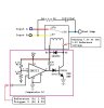
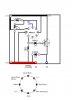
). I suspect the TIP31 is going to saturation, it's just switching at a faster rate than your meter.
One thing you can try is tie a .1uf cap from pin 6 to ground. The data sheet is not clear on what this pin is, but is may be switching purposes. If the cap doesn't fix your problem, you can put a 4Kohm resistor from pin 6 to +12V. There may be noise coming in on this line.
 
The transistor has nothing to turn it off. Add a base-emitter resistor, try 1k.
 
Status
Not open for further replies.

Latest threads

New Articles From Microcontroller Tips

Back
Top