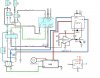
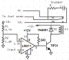
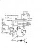
I need some help confirming this diagram I have made. What this circuit does:
There is a switching output from an automotive ECU to the Fuel Pump ECU. It is either 2.5V or it is 5.0V. Basically a trigger to change the fuel pump voltage between 9V and 12V. I am sending this signal to a Comparator as the trigger, and I am using a 5.0V regualtor for the referance voltage. Once the ECU kicks the voltage to 5.0V the Comparator will trigger and send out the 12V signal to the NPN transistor. This NPN Amp is rated at 25 Amps, so there s/b sufficient current to trigger the relay.
Where I am not sure, is if I need to add a diode, a resistor, or a capacitor anywhere. And if I even have this diagram drawn fairly accurately.
The purpose to this is to switch over to a voltage enhancer to increase the speed of the fuel pump motor increasing its output.
TIA
Stu
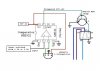
")