Hello everyone!
Please bear with me as I'm a complete newbie, and haven't done any electronics since I was at School!!
I'm wanting to build an LED meter for a rainwater tank, using a MaxSonar ultrasonic distance meter and a LM3914. The MaxSonar gives an analog reading of approx. 9.8mV/inch, so when my tank is emty the distance will be approx. 70 inches, so 0.68v.
A couple of issues I need your expert help with please:
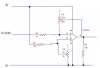
1. When the tank is full, the distance from the sensor will be small, so the voltage will be at its lowest. I therefore need to reverse the signal as in the Gas gauge project at this thread.
2. As the actual voltage range will depend on the final installation, I need to be able to adjust both the zero and range by say +/- 10 inches (98mV)
3. The sensors will be in the tank and the display in the house, so the cable to the sensors will probably be 15m long. Will a 5v supply pass down this OK, and in turn will the length of cable have any effect on the return voltage?
I've had a good look at the gas gauge thread, and the tech specs for the LM3914, but am really struggling to get my head around circuit diagram and the sizing of resistors.
Is anybody out there able to help me specify the Preamp and resistors, and work out a wiring diagram?
Many thanks in advance.
Please bear with me as I'm a complete newbie, and haven't done any electronics since I was at School!!
I'm wanting to build an LED meter for a rainwater tank, using a MaxSonar ultrasonic distance meter and a LM3914. The MaxSonar gives an analog reading of approx. 9.8mV/inch, so when my tank is emty the distance will be approx. 70 inches, so 0.68v.
A couple of issues I need your expert help with please:
1. When the tank is full, the distance from the sensor will be small, so the voltage will be at its lowest. I therefore need to reverse the signal as in the Gas gauge project at this thread.
2. As the actual voltage range will depend on the final installation, I need to be able to adjust both the zero and range by say +/- 10 inches (98mV)
3. The sensors will be in the tank and the display in the house, so the cable to the sensors will probably be 15m long. Will a 5v supply pass down this OK, and in turn will the length of cable have any effect on the return voltage?
I've had a good look at the gas gauge thread, and the tech specs for the LM3914, but am really struggling to get my head around circuit diagram and the sizing of resistors.
Is anybody out there able to help me specify the Preamp and resistors, and work out a wiring diagram?
Many thanks in advance.