Continue to Site

Welcome to our site!

Electro Tech is an online community (with over 170,000 members) who enjoy talking about and building electronic circuits, projects and gadgets. To participate you need to register. Registration is free. Click here to register now.

  • Welcome to our site! Electro Tech is an online community (with over 170,000 members) who enjoy talking about and building electronic circuits, projects and gadgets. To participate you need to register. Registration is free. Click here to register now.

Help Building a Water Meter Gauge using LM3914 and PreAmp

Status
Not open for further replies.
Enclosed the schematic I think I'm working to, based on information provided by Eric. Does the 2 resistors between + and gnd effectively provide the virtual ground you are referring to?
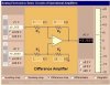
Yes. BTW, that op-amp needs to be one that allows input signals very close to ground like an LM358. Your bias point will only be 0.68V above ground, and many op-amps won't allow it.

I did think about reversing the LEDs, but have already started going down this path and have challenged myself to work my way through it!!

Thanks
I was young once too. When you get old, the challenge is always to find the easiest way to do it....
 
Last edited:
OK. I've set that up. Across the input I'm now only getting 0.5 to 0.6, yet when I split the input from this circuit it returns to giving me 0-0.68. Across the output I get 0.1 to 0.6, so inverting but practically no gain.

Am I being dim now? I've checked that my resistors are as per the schematic, the input voltage is 9v. The sonar returns 0-.68v when on its own.

Are there any voltages at different points in the circuit I can test to find the error in my ways?

Turning the LEDs round is sounding more likely - but that part of the circuit's up and running perfectly and I'm loathed to start mucking it up.
 
OK. I've set that up. Across the input I'm now only getting 0.5 to 0.6, yet when I split the input from this circuit it returns to giving me 0-0.68.
Sounds like you are loading down the source. maybe you need to use higher value resistors looking into the inverting input of the op amp, adjust feedback resistors up to keep same gain. The inverting input is a virtual ground so the source is loaded with the input resistor to ground.

Try making R4 a 10k resistor and adding a 30k (?) resistor in series with the gain trimmer P4. Tweak that 30k resistor's value up or down to get the gain you need centered on P4's range of adjustment. I can't tell from the schematic what gain you are trying to get.
 
Last edited:
I think you may not realize the op amps output signal will be referenced to the virtual ground point which is NOT GROUND, it is pin 3 of the op amp. The virtual is about 0.68V. So, when the input signal is 0.68V, the op amp sees "no input signal" and outputs zero volts with respect to the virtual ground, which is 0.68V with respect to ground. As the input signal goes below 0.68V, the op amp is receiving a negative going signal and inverts it giving a positive signal but the gain is with respect to virtual ground.

Your meter must be referenced (have it's negative side connected) to the virtual ground point to read correctly.
 
Last edited:
If I increase the resistance between inverting ground and output to about 30k I can get an output range of 0-3.5v! Which is nice.

Will this cause any issues with current draw?
 
Great. All I now need to work out is why all of a sudden as soon as I connect 5v power to the LM3914 it heats up massively! Just when I thought I was there.

Thanks for all your help
 
Great. All I now need to work out is why all of a sudden as soon as I connect 5v power to the LM3914 it heats up massively! Just when I thought I was there.

Thanks for all your help
You may need series resistors with the LEDs if you are running the LED drivers off 5V. When I use the 3914, I run the LED drivers off a lower voltage rail like 3.3V to reduce power dissipation in the IC.
 
I tried again this morning and it was fine - probably over tired!

All seems to be working OK now, but I'm getting flickering on the LEDs, which I don't get if I apply a signal direct using my 9v and a POT.

Do I need a capacitor in the circuit somewhere? I read somewhere about peak load or something but didn't understand!
 
I tried again this morning and it was fine - probably over tired!

All seems to be working OK now, but I'm getting flickering on the LEDs, which I don't get if I apply a signal direct using my 9v and a POT.
Sounds like something could be oscillating. Do you have a scope to look?
 
I realised that it wasn't working. It was either reporting 0v or 3.5v, but nothing in between.

I might give up and go for the simpler option after all. How do I wire the LEDs so that they are on by default, and go off as the voltage rises through the LM3914 as per Roff's suggestion?
 
I realised that it wasn't working. It was either reporting 0v or 3.5v, but nothing in between.

I might give up and go for the simpler option after all. How do I wire the LEDs so that they are on by default, and go off as the voltage rises through the LM3914 as per Roff's suggestion?
When the tank is full, the voltage is lowest. If you positioned the vertical LED bar normally (low voltage at the bottom), the bar would be fully lit when empty (because the voltage is high), and as the tank filled, the LEDs would go off one at a time, starting at the top. If you turned the bar upside down, the bar would still be fully lit when empty, but as the tank filled, they would go off one at a time, starting at the bottom. That sounds a little weird (my bad). :eek:
Perhaps you should use dot mode (with the bar still inverted). I think it would look normal, your LM3914 would run cooler, and you would save power.
 
Ah. That's what I was going to do originally, but I'd much prefer bar mode not dot. Is there a way I can drive 5v across each LED so it's normally on, so that when the LM3914 thinks each LED is positive, it puts 5v across it's own pin, turning the effective voltage to 0 and turning each LED off in turn?
 
I think I may be nearly there. I've now got the MaxSensor to output 0-.68v when on its own, and an op-amp circuit ased on Eric's information to take 0-.68v from a POT and output 3.4v to 0v.

However, when I swap the POT over for the output from the Maxsensor, although according to my multimeter they are giving the same outputs, the OpAmp will then only output 0v to 0.7v, and both the input and output seem to be doing a lot of oscillating on the meter before settling on a voltage.

Does anybody have any suggestions?
hi,
Dont quite follow you explanation regarding pot swopping over.?

Any chance you could post a simple diagram showing how the FULL circuit is connected.:)
 
Eric,

To see whether the circuit works, I used a pot to divide a 5v supply so that I could simulate a Vin range of 0-0.68v. Doing this, the OpAmp circuit works perfectly, and is set up as per the attached.

However, when I remove the Op Amp and replace it with my actual meter, which I separately check is also showing the above voltage range on a multi-meter, I get a completely different response from the Op-Amp. It's as though the Op-amp is clipping my input at anything below about 0.5v, even though I know it works when providing that low voltage via the POT mock-up.

Thanks
 

Attachments

  • New Picture.jpg
    New Picture.jpg
    37.4 KB · Views: 164
Last edited:
hi,
Thats not the same circuit as the circuit I posted.???

I will look it over, but have you changed the inputs and component values.:)
 
hi,
Thats not the same circuit as the circuit I posted.???

I will look it over, but have you changed the inputs and component values.:)

I'm powering the OpAmp at 9v single supply, so went back to your original values before you updated them to 5v for me.
 
I'm powering the OpAmp at 9v single supply, so went back to your original values before you updated them to 5v for me.

OK,
And is the opa a 741.?
I am going thru your cct on the LTspice sim.
 
Status
Not open for further replies.

Latest threads

New Articles From Microcontroller Tips

Back
Top