Continue to Site

Welcome to our site!

Electro Tech is an online community (with over 170,000 members) who enjoy talking about and building electronic circuits, projects and gadgets. To participate you need to register. Registration is free. Click here to register now.

  • Welcome to our site! Electro Tech is an online community (with over 170,000 members) who enjoy talking about and building electronic circuits, projects and gadgets. To participate you need to register. Registration is free. Click here to register now.

HD44780 and 18f4550 problems

Status
Not open for further replies.

HerbertMunch

New Member
Hi im trying to control a 44870 lcd with a pic18f4550.

It seems everytime i try and do LCD i run into problems. Im running out of hair to pull out.

I have tried the microchip c18 XLCD library, and my own lcd code, but neither work.
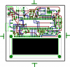
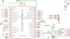
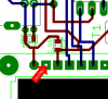
I have included my code, and circuit diagram.

The code project is a slightly modified Microchip usb framework.
The code that im trying to get working resides inside LCD.c and PinDefs.h.

it would seem that Im failing to initialise the lcd properly.

Can anyone see any obvious mistakes im making?

Many thanks.
Chris


LCD.C code
Code:
#include "LCD.h"

void Delay1mS(void);
void Delay15mS(void);
void Delay5mS(void);
void Delay200uS(void);
void PulseE(void);
void SendCommand1(byte);
void SendCharacter(char);

byte Swap(byte);

//Sends a byte command to the HD44780 display.
void SendCommand(byte command)
{


	Delay15mS();
	command = 0;

}


//Swaps nibbles of byte
byte Swap(byte command)
{
	byte temp = command <<4;
	temp |= command >>4;

	return temp;
	
}

//Initialises the display
void OpenLCD(void)
{

	
	//Make port outputs
	LCDPORT = 0;
	LCDTRIS = 0;

	//Wait for display
	Delay15mS();
	
	//Send 0x03
	SendCommand1(0x20);
	SendCommand1(0x28);
	SendCommand1(0x06);
	SendCommand1(0x0c);
	SendCommand1(0x01);
	
	SendCharacter('a');


}

void SendCommand1(byte command)
{


	LCDTRIS &= 0x0F;
	LCDPORT &= 0x0F;

	//Swap nibbles
	
	LCDPORT |= command;
	//LCDPORT |= command & 0xF0;
	PulseE();
	
	Delay15mS();
	
}


void SendCharacter(char character)
{
	LCDPORT =0;
	LCD_RS  =1;
	LCDPORT |= character & 0xF0; 
	PulseE();
	LCDPORT |= Swap(character) & 0xF0;
	PulseE();
	Delay15mS();
	
}


void PulseE(void)
{
	LCD_E = 1;
	Delay200uS();
	LCD_E = 0;
	Delay1mS();
}


PinDefs.h
Code:
/*

Pin definitions and macros
Chris Dec 07

*/

#include <P18F4550.h>

//Power check pins
#define PIN_SELFPOWER PORTBbits.RB5
#define PIN_USBPOWER PORTDbits.RD3

//Switch pins
#define PIN_SWITCH1 PORTBbits.RB4
#define PIN_SWITCH2 PORTBbits.RB3


//LED pins
#define PIN_LED1 LATBbits.LATB2
#define PIN_LED2 LATBbits.LATB1
#define PIN_ONLED LATBbits.LATB0

//Piezo pins
#define PIN_PIEZO1 LATCbits.LATC0
#define PIN_PIEZO2 LATCbits.LATC1
//LM35
#define PIN_LM35 PORTEbits.RE1

//LCD pins - bit 3 is not used for LCD and should not be manipulated
#define PIN_BACKLIGHT LATCbits.LATC6
#define LCDPORT PORTD
#define LCDTRIS TRISD
#define LCD_RS PORTDbits.RD0
#define LCD_RW PORTDbits.RD1
#define LCD_E PORTDbits.RD2


//Macros
#define ScreenOn() PIN_BACKLIGHT = 1;
#define ScreenOff() PIN_BACKLIGHT = 0;
 

Attachments

  • Board.png
    Board.png
    22.6 KB · Views: 531
  • project1.zip
    420.7 KB · Views: 277
  • Schem.png
    Schem.png
    33.8 KB · Views: 2,372
Last edited:
An obvious problem is no contrast control, depending on your specific LCD (and the ambient temperature) you may very well not be able to see if it's working or not?.

Add a contrast control, and then try adjusting it - if the LCD isn't initialised you should be able to adjust it so you can see a single row of solid black squares (this works without the PIC there at all).
 
I had a quick look at the code and the only thing I immediately spotted is that to send a command you have to still send both nibbles and clear RS. Also, your initialisation doesn't appear correct, there is a sequence of writes and delays that have to be preformed.

Mike.
 
OK cheers mate, ill have a go atthe contrast thing. I had completely overlooked that:eek: .

My code is messy and horrible, because it is the product of many hours of tedious pointless modification. It doesn't work with the Microchip code either.

Anyway thanks for the quick reply:D
 
Hi Herbert,

You better make one function to write 1 byte to the LCD independently if it's an instruction or a command.
The only difference between both is the RS line, 0 for instruction and 1 for a command.
So first set the RS line then call your "WriteByte" routine.

This is my "WriteByte" routine (for 8051 :()
Code:
;LCD_Write_Acc
;Write acc value to LCD in two consequtive writes
;
LCD_Write_Acc:	push	acc		;Store acc for later
		orl	LCD_Data,#0F0h	;Send high nibble
		orl	a,#00Fh
		anl	LCD_Data,a
		setb	LCD_EN
		clr	LCD_EN
		pop	acc		;Send low nibble
		swap	a
		orl	LCD_Data,#0F0h
		orl	a,#00Fh
		anl	LCD_Data,a
		setb	LCD_EN
		clr	LCD_EN
		RET			;END LCD_Write_Acc

I use this routine for both instructions and commands.
The caller sets the RS line accordingly and then calls the "LCD_Write_Acc" routine.

Please also notice that you need to pulse the Enable line twice.
Something you do correctly in your "SendCharacter" routine but not in your "SendCommand1" routine :(


Regarding the initialize sequence you need to send the following bytes:
1) 3 times 30h
2) 1 time 20h
3) 1 time "Function set" byte, depend on display lines & font
4) 1 time 08h
5) 1 time 01h
6) 1 time "Entry mode set" byte, depend on what you want

Between all these bytes you need to wait a certain time (I always wait 30ms).

After that you can use the busy flag to check the status of the LCD.

Hope this helped...
 
When i started poking around at the board, I discovered something foolish.

What I appear to have done is instead of connecting 5v+ to pin2, i connected it to pin3(CONTRAST).

My schematic shows that both pin2 and 3 are connected to vdd, so why has eagle forgotten to connect an air wire to pin2?

Cheers
 

Attachments

  • FOOL.png
    FOOL.png
    16.4 KB · Views: 320
mcs51mc said:
Hi Herbert,

You better make one function to write 1 byte to the LCD independently if it's an instruction or a command.
The only difference between both is the RS line, 0 for instruction and 1 for a command.
So first set the RS line then call your "WriteByte" routine.

This is my "WriteByte" routine (for 8051 :()
Code:
;LCD_Write_Acc
;Write acc value to LCD in two consequtive writes
;
LCD_Write_Acc:	push	acc		;Store acc for later
		orl	LCD_Data,#0F0h	;Send high nibble
		orl	a,#00Fh
		anl	LCD_Data,a
		setb	LCD_EN
		clr	LCD_EN
		pop	acc		;Send low nibble
		swap	a
		orl	LCD_Data,#0F0h
		orl	a,#00Fh
		anl	LCD_Data,a
		setb	LCD_EN
		clr	LCD_EN
		RET			;END LCD_Write_Acc

I use this routine for both instructions and commands.
The caller sets the RS line accordingly and then calls the "LCD_Write_Acc" routine.

Please also notice that you need to pulse the Enable line twice.
Something you do correctly in your "SendCharacter" routine but not in your "SendCommand1" routine :(


Regarding the initialize sequence you need to send the following bytes:
1) 3 times 30h
2) 1 time 20h
3) 1 time "Function set" byte, depend on display lines & font
4) 1 time 08h
5) 1 time 01h
6) 1 time "Entry mode set" byte, depend on what you want

Between all these bytes you need to wait a certain time (I always wait 30ms).

After that you can use the busy flag to check the status of the LCD.

Hope this helped...


Nice one mate.
thanks
 
Its still not working!
I have made needed modifications to the board, but i still cant init the module.

LCD.C
Code:
/*
	Lcd functions

*/

#include "LCD.h"

void Delay1mS(void);
void Delay15mS(void);
void Delay5mS(void);
void Delay200uS(void);


void PulseE(void);
void SendCommand(byte);
void SendCharacter(char);
void SendCmdNibble(byte);
int  LCDBusy(void);

void SendLCD(byte);

byte Swap(byte);


//Swaps nibbles of byte
byte Swap(byte command)
{
	byte temp = command <<4;
	temp |= command >>4;

	return temp;
	
}

//Initialises the display
void OpenLCD(void)
{


	//Make port outputs
	LCDPORT = 0;
	LCDTRIS = 0x08; //All outputs except for pin3 which is USb bus sense

	//Wait for display
	Delay15mS();
	Delay15mS();
	PIN_LED1 =1;
	PIN_LED2 = 0;

	//Send 0x03
	SendCmdNibble(0x03);
	SendCmdNibble(0x03);
	SendCmdNibble(0x03);
	
	SendCmdNibble(0x02);
	SendCommand(0x23);
	SendCommand(0x08);

	SendCommand(0x01);
	

	SendCommand(0x06);

	PIN_LED1 =0;
	PIN_LED2 = 1;


	while (LCDBusy())
	
	
	PIN_LED1 =0;
	PIN_LED2 = 0;


}

void SendCmdNibble(byte command)
{
	LCD_RS = 0;
	LCDPORT &= 0x0F; //Discard high nibble (data)
	LCDPORT |= Swap(command) & 0xF0;	//Set high nibble to port (
	PulseE();
	Delay15mS();
}

int LCDBusy(void)
{
	int result=0;
	LCD_BUSY = 0;//reset busy pin
	LCD_TRIS_BUSY = 1; //set pin to input

	LCD_RS = 0;
	LCD_RW = 1;

	result = (LCDPORT & 0x80) ? 1: 0;
	
	LCD_TRIS_BUSY = 0; //Set pin to output
	
	return result;
		
	
}

void SendCommand(byte command)
{
	//setup to send command
	LCD_RS = 0;
	//send command
	SendLCD(command);
}

//Sends a character to the LCD
void SendCharacter(char chr)
{
	LCD_RS = 1;//Setup to send character
	//Send character
	SendLCD((byte) chr );
}

//Sends message/command to lcd. Requires the RS line to be set appropriately
void SendLCD(byte message)
{
		
	//Send high nibble first
	LCDPORT |= message & 0xF0;
	
	PulseE();
	
	LCDPORT &= 0x0F;//clear data pins, but leave control pins alone
	LCDPORT |= (Swap(message & 0x0F)); //swap nibbles and discard old high nibble
	
	PulseE();
	Delay15mS();
	
}


void PulseE(void)
{
	LCD_E = 1;
	LCD_E = 0;
	Delay1mS();
}


I just dont understand, its completley doing my head in now:mad: .

Any ideas?
 

Attachments

  • project1.zip
    420.7 KB · Views: 181
Your initialisation is still wrong.
The data sheet states,

After Power On,
Wait more than 15mS
Send Nibble 0x30
Wait more than 5mS
Send Nibble 0x30
Wait more than 100uS
Send Nibble 0x30
Send Nibble 0x20

The display is now initialised in 4 bit mode.
In you case you will send 0x03 instead of 0x30 as you swap nibbles in your routine.

Mike.
 
Please keep in mind that the LCD won't do anything as long as it didn't receive 8 bits = 1 byte, even in 4 bit mode.
So forget your "SendCmdNibble" routine.
After sending 1 nibble, the LCD won't execute nothing, since it's still missing 4 bits.
You always need to send 8 bits or 1 byte!!

So when Pommie writes "Send Nibble 0x30" its not correct :)

You always need to send 8 bits (1 byte), that's why I made one routine "LCD_Write_Acc".
In ALL cases I send 8 bits to the LCD.

With your code
Code:
	SendCmdNibble(0x03);
	SendCmdNibble(0x03);
	SendCmdNibble(0x03);
	
	SendCmdNibble(0x02);
you send 0x33 and 0x32 to the LCD.

With your routines your initialize routine would be something like
Code:
LCD_RS = 0
SendLCD(0x30);
Delay15mS();
SendLCD(0x30);
Delay15mS();
SendLCD(0x30);
Delay15mS();
SendLCD(0x20);
Delay15mS();

And remove the Delay line in the SendLCD routine, since you won't need it later on, when using the busy flag :)
 
mcs51mc said:
So when Pommie writes "Send Nibble 0x30" its not correct :)

Please study the data sheet.:rolleyes:
**broken link removed**
Mike.

Edit, Maybe I should point out that until the data width is set to 4 bits then sending a nibble and sending a byte are the same thing.
 
Last edited:
Thanks all for your replies.
You must think im so stupid! I know i do.
Has no one ever have any problems with HD44780? Last time I started on LCD, i was doing it ASM, and I spent about 2 days trying to get it to work (and many posts here as well).

Nigel, heres what happens:

Power ON
Top row of 16 blocks shows.
Bottom row flashes about 3 times and then turns off.
Busy flag never clears, so led stays on, and while loop never finishes.

After making modifications to the board, The LCD now turns on, before it was just the backlight!
I can also see the 16x2 'place holder' blocks now i have connected the contrast directly to ground(before it was routed to vdd).

Any way thanks again everyone for the replies, i really appreciate all your help on this matter.

Cheers,
Chris

p.s will post again when it doesnt work!
 
Pommie said:
Please study the data sheet.:rolleyes:
Maybe I should point out that until the data width is set to 4 bits then sending a nibble and sending a byte are the same thing.

So my send command nibble routine is ok then yeah?
 
HerbertMunch said:
When would i need to pass a 16 bit value?
I was refering to only pulsing e once, i.e sending only 4 bits
Sorry Chris, my mistake :eek: I promise that I'll check your code more carefully later and hope to be helpful.
 
Last edited:
HerbertMunch said:
I can also see the 16x2 'place holder' blocks now i have connected the contrast directly to ground(before it was routed to vdd).
The only correct way to connect the contrast, is using a multiturn 20k pot meter between power & ground, slider to pin 3 (contrast) of the LCD. That way you can regulate the contrast easily.

Regarding the 4/8 bits, nibble/byte stuff: I'm still convinced that you don't need the "SendCmdNibble" routine since it work well the way I do it :)
 
mcs51mc said:
The only correct way to connect the contrast, is using a multiturn 20k pot meter between power & ground, slider to pin 3 (contrast) of the LCD. That way you can regulate the contrast easily.

Regarding the 4/8 bits, nibble/byte stuff: I'm still convinced that you don't need the "SendCmdNibble" routine since it work well the way I do it :)

This is just nonsense. A multiturn pot for contrast, ludicrous.

Regarding 4/8 bit, it makes no difference, the display hasn't been informed if the interface is 4 or 8 bit and therefore it ignores the bottom 4 bits.

I'm unsure, but I think you may have been jesting in your post, if you were then please read my reply appropriately.

Mike.
 
Status
Not open for further replies.

Latest threads

Back
Top