Continue to Site

Welcome to our site!

Electro Tech is an online community (with over 170,000 members) who enjoy talking about and building electronic circuits, projects and gadgets. To participate you need to register. Registration is free. Click here to register now.

  • Welcome to our site! Electro Tech is an online community (with over 170,000 members) who enjoy talking about and building electronic circuits, projects and gadgets. To participate you need to register. Registration is free. Click here to register now.

HD44780 Character LCDs in Parallel?

For The Popcorn

Well-Known Member
Most Helpful Member
I'm working on a device with a 4 line × 20 character HD44780 LCD that has a very dim backlight. The display is also at a poor angle for visibility. It's soldered in, so replacement isn't trivial.

I have a display that should be a direct replacement that is beautifully back-lit. I had two thoughts:

● Paralleling the displays to test for compatibility.

● Adding a second LCD in parallel as a second remote display.

I don't believe any damage would come from paralleling two character LCDs. And depending on how the interface is implemented, I think the scheme would work fine.

Has anybody tried this?
 
Thank you for your input.

I tried to make it pretty clear that I understand about Vo, hence my comment about adding a pot if there's not a (workable) adjustment on this commercial product.

I thought it pretty clear that I understand calculating series resistors for LEDs. Yes, a 10 ohm resistor with a typical Vf of 4.2 volts is somewhat miserly for a display that would like 240mA, but the backlight should be more than faintly visible.

Both the lack of a pot and a dim display with what should be a reasonable current lead me to believe both may be firmware controlled but as I stated, I haven't found any button combination that leads to a set-up menu.

I'll know more when I trace out the board.
Obviously you don't understand about Vo, as you haven't connected a pot to it. I don't quite see the relevance of 'commercial product'?, you need to connect a pot to Vo (as per the datasheet) to use an LCD module - they don't come with pot's fitted as you might be doing it via PWM, and the pot wouldn't be in a very accessible place. I wouldn't expect you to be able to connect the two Vo's together, as it's unlikely they would be identical in operation - use a seperate pot.

You usually do have a pot though on the I2C converter boards though, along with the conversion IC.

I'm also a bit horrified using a 10 ohm resistor feeding the back LED's, and talking about 240mA - for our current 2x16 ones we use a 180 ohm resistor, but for the older version of the display we used a slightly smaller one (120 ohm perhaps?), as the new displays have more efficient backlights. I've even considered increasing it's value, as it's more than bright enough at 180 ohms.

Add a pot to Vo, and adjust it, you might well find it's far too bright then, and you need a higher value LED resistor. Very often, with no connection to Vo, you get no visible display at all - I'm sure many people here have been suitably depressed when they power on their new project, and find nothing on the display - I certainly have :D
 
I have encountered a number of LCDs with the 44780 controller where a single
R was connected from Vo to Vcc/Vdd. Many of these displays start up with

1693137486476.png


Nominally that R is 10K or greater. One then adds to pot from VDD/Vcc to pin to Vss/Gnd
to adjust the contrast and show the characters. Can be a 5K or lower kind of pot to "swamp"
out effect of pullup, if present. I have also observed what seems like newer modules the
Vo is closer to Vdd/Vcc. I have used, in one off designs, a diode from Vcc/Vdd to Vo and that
has produced a pretty accurate good looking display.

I think the manufacturers process varies on required Vo voltage, so pot is good idea.


Regards, Dana.
 
Last edited:
Nigel Goodwin , pardon me, but it's as if you haven't read most of what I've written.

1. The device the LCD is connected to is a 20 year old commercial product. I do not have a schematic and I have no ability to alter the firmware. The "lack of pot for Vo" is that there are no pots on the board.

2. My test was a "quick and dirty" test, connecting a new LCD (which happens to have a 16 pin cable attached) in parallel with the existing display (as in the title of this post) by connecting the 16 pin cable to the 16 pin header pins on the existing display. Vo was in parallel with the existing display. As there's no pot on the board that board displays, I didn't have any way to adjust Vo; if I swap out the display, I might have to graft a pot in....or try to find someone to explain how to access a setup menu if it's controlled programmatically on this 20 year old board of a somewhat obscure product.

3. My apologies for horrifying you with the LED current. I hope it did not cause you undue stress! This snippet of table is from the ABSOLUTE MAXIMUM section of the data sheet. Absolute maximum current is listed as 600mA.

SmartSelect_20230827_054011_Dropbox.jpg


This snippet of table is from the RECOMMENDED OPERATING CONDITIONS table in the data sheet: Horror of horrors, it's right there! 240mA.

SmartSelect_20230827_054121_Dropbox.jpg


4. What's an I2C converter board got to do with the application under discussion?
 
Last edited:
And for the record, the 10 ohm series resistor was selected by the designer 20 years ago. The value is silkscreened on the board and the resistor is indeed 10 ohms.

As I have stated, I need to trace out the connections on the board.

CM230823-170711009.jpg
 
Last edited:
Thanks all for the input. I really do know how LCD displays work, that Vo needs to be adjusted for the particular display, how to read a datasheet and how to calculate series resistors.

As per the title of this thread, I was asking about operating two HD44780 character LCDs in parallel, primarily to verify that the new display was compatible with the old.

In this case, it did work, but depending on how the display operates, that would not be true in every case.

If I wanted to permanently add a second display, I would break out the Vo pin to a 10k pot and supply the LED backlight separately.

Thanks for the replies.
 
Let's start with a few pictures to clarify things.

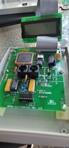
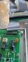
Here's my test setup. New display paralleled with old, pin for pin.

Lcd test 1.jpg

Lcd test 2.jpg

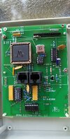
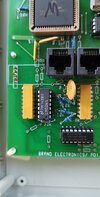
The top view of the board.

Theracycle board top.jpg

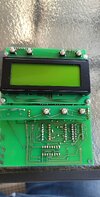
The bottom view of the board.

Theracycle board bottom.jpg

And finally, a crazy board "feature".

Board feature.jpg

This board does work, but the layout seems really crude, even for 20 years ago!


The following chips are on the board.

PIC17C756A-33/L MCU 8-bit PIC17 PIC RISC 32KB EPROM 5V 68-Pin PLCC

MM74HC4053N Triple 2-channel analog multiplexer/demultiplexer

LM324 QUAD OPAMP

2N3904 NPN TRANSISTOR

24LC128 EEPROM

DM74S00N QUAD 2-INPUT NAND GATE


Trying to trace the tracks on the board is nearly impossible with the LCD soldered in place and the crazy track routing. Fortunately, there's not much to trace as far as my issues are concerned.

Pin 3 Vo – tied to ground.

Pin 15 LED+ – tied to +5v

Pin 16 LED– – tied to ground via 10 ohm resistor. The 10 ohm resistor is verified as 10 ohms.


The replacement display I may use operates at a "horrifying" typical current of 240mA with typical al Vf being 4.2v. A 10 ohm resistor would yield 80mA, a third of the typical current. A 3.3 ohm resistor would yield 240mA, with the LEDs dissipating just over a watt.

The power supply for this board is buried in the bowels of the machine. I don't know if it would supply 3× the current.
 
Let's start with a few pictures to clarify things.

Here's my test setup. New display paralleled with old, pin for pin.

View attachment 142576

View attachment 142577

The top view of the board.

View attachment 142578

The bottom view of the board.

View attachment 142581

And finally, a crazy board "feature".

View attachment 142582

This board does work, but the layout seems really crude, even for 20 years ago!


The following chips are on the board.

PIC17C756A-33/L MCU 8-bit PIC17 PIC RISC 32KB EPROM 5V 68-Pin PLCC

You find PIC's in almost everything, they are a very popular processor - this is obviously an old unit, as it uses an OTP device.

MM74HC4053N Triple 2-channel analog multiplexer/demultiplexer

LM324 QUAD OPAMP

2N3904 NPN TRANSISTOR

24LC128 EEPROM

DM74S00N QUAD 2-INPUT NAND GATE


Trying to trace the tracks on the board is nearly impossible with the LCD soldered in place and the crazy track routing. Fortunately, there's not much to trace as far as my issues are concerned.

Pin 3 Vo – tied to ground.

Pin 15 LED+ – tied to +5v

Pin 16 LED– – tied to ground via 10 ohm resistor. The 10 ohm resistor is verified as 10 ohms.


The replacement display I may use operates at a "horrifying" typical current of 240mA with typical al Vf being 4.2v. A 10 ohm resistor would yield 80mA, a third of the typical current. A 3.3 ohm resistor would yield 240mA, with the LEDs dissipating just over a watt.

Are you absolutely sure of that?, it sounds absolutely crazy - do you have a link for the display?.

Looking at pictures on-line, and at the 4x20 LCD examples I have here, they include a 51 ohm SM resistor in series with the LED's on the LCD PCB (giving a maximum of around 16mA @ 4.2V Vf - you then add extra resistance feeding it, to reduce it to what you want).

I've just checked a 2x16 LCD, and that has (as you would expect) a 100 ohm resistor on the PCB - half the display size, half the current needed (roughly), and again, you add extra to take it down to where you want it.
 
I posted pictures showing the existing 10 ohm resistor, and stated that it does in fact measure 10 ohms.

I posted maximum and recommended operating levels from the datasheet and attached the datasheet for the new display.

I explained that this is a 20 year old device. What I didn't explain was I talked to the manufacturer, and records from that time have been lost.

All of your comments have already been addressed.
 

Latest threads

New Articles From Microcontroller Tips

Back
Top