cimulation
New Member
I am trying to make a HBridge using BC327 and BC337 transistors. I am planning to use it with linear actuator PQ12 (datasheet attached).
I have spent extensive amount of time getting it to work with servo circuit. I basically tried to use the Servo HS55 and couple it with the PQ12. I could get the PQ12 to move in one direction with the servo PWM input but not in both the directions.
So finally I decided that I will use a HBridge to drive the PQ12 from my PIC16F MCU. I will toggle the outputs of PIC output pins to move the linear actuator.
I had 2 worries::
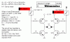
1) Will the hBrighe (schematic attached herein) be adequate for the linear actuartor.
2) should I add diodes or other protection elements to my PIC processor as safety/to protect from the hbridge.
I welcome your suggestion.
Best Regards,
Sumit.
I have spent extensive amount of time getting it to work with servo circuit. I basically tried to use the Servo HS55 and couple it with the PQ12. I could get the PQ12 to move in one direction with the servo PWM input but not in both the directions.
So finally I decided that I will use a HBridge to drive the PQ12 from my PIC16F MCU. I will toggle the outputs of PIC output pins to move the linear actuator.
I had 2 worries::
1) Will the hBrighe (schematic attached herein) be adequate for the linear actuartor.
2) should I add diodes or other protection elements to my PIC processor as safety/to protect from the hbridge.
I welcome your suggestion.
Best Regards,
Sumit.