Continue to Site

Welcome to our site!

Electro Tech is an online community (with over 170,000 members) who enjoy talking about and building electronic circuits, projects and gadgets. To participate you need to register. Registration is free. Click here to register now.

  • Welcome to our site! Electro Tech is an online community (with over 170,000 members) who enjoy talking about and building electronic circuits, projects and gadgets. To participate you need to register. Registration is free. Click here to register now.

Have a look at my new Oscilloscope (New to me that is!)

Status
Not open for further replies.

AlainB

Member
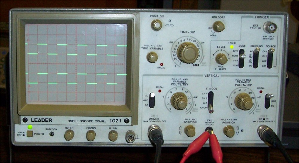
I just bought it last week. It is a Leader 1021. Maybe 20 years old or more. It came with a new 1X-10X probe, 2 good quality wires with aligator clips, a few other home made wires and a few splitter. I paid 35$ CAD for everything. Just the price of the probe is about that amount. So I had a good deal.

I did not found a manual for it but luckily 2 documents describing how this particular oscilloscope work:

https://www.electro-tech-online.com/custompdfs/2009/06/F04LabManChap1-8.pdf

E-6: Cathode Ray Oscilloscope and Differential Amplifiers

An oscilloscope was so mysterious to me and I wanted one for such a long time that I could not resist. Anyway, it is really small money for such a tool and just for the learning of the last few days, I consider it as already paid.

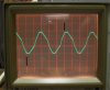
Please have a look at the picture. Is this a normal square wave? Is it what is expected from this oscilloscope?

From my very small knowledge, may I say that the voltage divisions is pretty well calibrated but the time division is a little off? Being a little off, I could adjust it with the time variable knob if I want to but really it is not such a big deal?

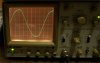
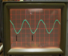
On the other picture it show a sine wave that I got from a computer sound card. Something wrong there?

I already used it to see how very crisp is the action of some photointerruptors that I was talking about in another post. I used it also to look at the parallel port pins of my old laptop.

Is it fair to say that this machine is not completely obsolete and it can still be use for many different kind of tests?

Alain

leader-1021-1-jpg.30402
 

Attachments

  • Leader 1021-1.jpg
    Leader 1021-1.jpg
    102.4 KB · Views: 3,082
  • Leader 1021-2.jpg
    Leader 1021-2.jpg
    59.5 KB · Views: 712
Last edited:
It looks like a fine instrument. The "sine" wave might just be poorly synthesized by your sound card. I don't know much about sound cards, but I see tell-tell signs of a synthesized signal in your trace.
 
It looks like a fairly reasonable scope, certainly good enough for audio and low speed digital circuits e.g. 4MHz MCUs.

The square waveform looks right to me.

For frequency is better calibrated using a known stable source such as the mains frequency. There's no need to connect it to the mains though, just hold the probe in your hands and you should see a distorted 60Hz sinewave.

The sine wave from the the sound card looks pretty distorted, try turning the volume down.

The next item on your shopping list should be a signal generator but you can make one of these pretty easily yourself.
 
For frequency is better calibrated using a known stable source such as the mains frequency. There's no need to connect it to the mains though, just hold the probe in your hands and you should see a distorted 60Hz sinewave.

That was a nice tip! Look at my result! The oscilloscope is set at 5ms. Pretty decent isn't it?

It is flickering a lot at 5ms though. I had to use the Portrait setting on my camera to have the whole screen on the picture.

Any other tips, from anybody, are quite welcome too!

Thanks!

Alain

(sorry, I did not adjust the volts position before taking the picture)

leader-1021-60hz-jpg.30476
 

Attachments

  • Leader 1021-60Hz.jpg
    Leader 1021-60Hz.jpg
    49.2 KB · Views: 1,980
Last edited:
You've got 1½ cycles marked there.

Here's 1 cycle.

As you can see it comes to just under 17ms which is just about right.

The easiest way of doing it is by measuring three cycles which should be exactly 50ms.
 

Attachments

  • Scope pic.PNG
    Scope pic.PNG
    689.7 KB · Views: 341
From my very small knowledge, may I say that the voltage divisions is pretty well calibrated but the time division is a little off? Being a little off, I could adjust it with the time variable knob if I want to but really it is not such a big deal?
You are looking at the ≈1kHz signal from the oscilloscope calibrate output. The ≈ symbol means that its frequency is approximately, not exactly 1kHz, so the oscilloscope time-base calibration is likely fine.
 
You're going to see "flicker" at sweep speeds slower than 1ms/DIV. If there's a front panel holdoff adjustment, it should be set at minimum for the least "flicker".

An obsolete scope? Nah. If it works and it's triggered sweep, it may be old, but not obsolete. I'll take most any Tektronix mid-1970s offering over a new digital model any day. I don't own a digital scope -- used plenty, they're cute, but not worth the price. I have three Teks at my disposal: 213, 465DM44 and a 7904 loaded with plug-ins. I love 'em all!

Dean
 
You are looking at the ≈1kHz signal from the oscilloscope calibrate output. The ≈ symbol means that its frequency is approximately, not exactly 1kHz, so the oscilloscope time-base calibration is likely fine.

I see!

This little symbol was one of my interrogation. It look a little bit like a sine wave. But wy, was I asking myself, put what I thought was a sine wave symbol for a square wave output?

Alain
 
An obsolete scope? Nah. If it works and it's triggered sweep, it may be old, but not obsolete. I'll take most any Tektronix mid-1970s offering over a new digital model any day. I don't own a digital scope -- used plenty, they're cute, but not worth the price. I have three Teks at my disposal: 213, 465DM44 and a 7904 loaded with plug-ins. I love 'em all!

Dean
Digital scopes don't have any flicker, and can store a trace indefinitely (and of course they certainly are cute).

Our company got rid of the last analog oscilloscope several years ago. Don't miss them the least little bit.

I suppose you like vinyl records and tube amps also.
 
You're going to see "flicker" at sweep speeds slower than 1ms/DIV. If there's a front panel holdoff adjustment, it should be set at minimum for the least "flicker".

An obsolete scope? Nah. If it works and it's triggered sweep, it may be old, but not obsolete. I'll take most any Tektronix mid-1970s offering over a new digital model any day. I don't own a digital scope -- used plenty, they're cute, but not worth the price. I have three Teks at my disposal: 213, 465DM44 and a 7904 loaded with plug-ins. I love 'em all!

Dean

For finding glitches an analog scope can't compare to a digital. I think each type of scope has its place. There are just certain troubleshooting methods available with a digital scope that a analog will fail miserably.

The Tek 460 series was a real nice digit scope about ten years ago. Have you tried one of those?

For me, I like to have both an analog and a digital scope at my disposal.
 
Last edited:
Analog scopes are easy to learn and easy to use. They are completely sufficient for 99.99% of the hobbist's work. The allow for easy debug of nearly any analog circuit, and most digital. They are simple to service and calibrate. And, they are easy on the pocketbook.

As far as looks go, nothing beats these retro-beauties :)
 
Last edited:
I like digital scopes for their ability to store and freeze waveforms.

I also like analogue scopes because they're so easy to use and I 100% understand how they work. I also like the way fast a falling edge gives a dimmer trace than slow falling edge. This enables you to get a better estimate of the rise/fall time.

I don't own a digital scope myself but I would swap my analogue scope for a digital. If I bought a digital scope I'd still keep one of my analoge scopes though.

EDIT:
Back on topic.

You're better off measuring three cycles which should be 50ms and calibrating if required.

Another option is to build a 1MHz oscillator using a crystal and using that.
 
Last edited:
... I paid 35$ CAD for everything. Just the price of the probe is about that amount. So I had a good deal.[/IMG]

Hey, outta curiosity, where'd you buy the scope from? I've been looking for a reasonably-priced one for quite a while now (in Canada) ^^
 
Hi,

I got it from the Montreal Kijiji adds site:

**broken link removed**

He was asking 40$, I paid 35$

Alain

Edit: The add for my oscilloscope will vanish in one month or 2. Here is a search in the Montreal region that should be good for a longer time:

**broken link removed**
 
Last edited:
Tek's "460" series were from ca. 1975 through around 1982 and ALL but the 468 were analog. The 468 was the first portable digital offering from Tek and was basically a 465 with the digital portion on top of the scope in place of a DM44 DMM.

Yes, digital and analog have their places. I liked the Tek digitals I used for the ability to print the screen directly to printer -- a real "plus" in education. But if you're going to use them for catching fast glitches, you'd better have exotic triggering and a sampling rate in the low- to mid-GS/s range.

It takes a really expensive digital scope to store a high-speed single-shot waveform where a Tek analog 466, 7623A or 7834 can do it with ease. Still, as long as you don't dwell on the ability to store waveforms digitally, an analog scope will serve you well in 99.99% of all applications and for far less money.

Another big argument against digitals is the fact that they're in the same category as scientific calculators, cellular phones, CD and DVD players and the like. After the hardware is designed, it takes very little money to add a gazillion features in software/firmware to make it more "attractive" to the uninitiated -- make it oodles more difficult to learn and use. Every year, I'd have at least two students who would buy some $30, 374-function scientific calculator for my electronics class and then just use twenty functions -- and expect ME to help him get out of messes with the thing! Why does my Sony CD player require a remote with 60 buttons?

Dean
 
...if you're going to use them for catching fast glitches, you'd better have exotic triggering and a sampling rate in the low- to mid-GS/s range.

The (relatively) new DPO scopes can catch glitches rather well, freeze and store them. Though I don't see much need for them in a hobbyist's set of tools given the price tag. I use the nice digital scopes with DPO at work (they really are great for sharing info because the screen capture can be ported into many different formats) but I have an analog scope at home which is more than adequate for what I do.
 
Hi,

Could you suggest me a design or a schematic to build one? This would be a nice little project.

Alain
You can easily make one with a CMOS gate.

**broken link removed**

Note that you'll need to add another gate on the output to buffer it so the capacitance of the scope probe doesn't stop it oscillating.

I forgot to mention another good way of calibrating the timebase.

Connect the scope to a stable accurate oscillator which has a period equal to a multiple of the scope's T/div. For example for 1MHz set the scope to 2×1÷1µs = 2µs/div.

Disable the scope's trigger.

Trim the timebase until the waveform is stable and stays in the same precision.

Double check that the waveform has the right frequency by looking at the divisions on the scope.
I don't believe that will work in general. You are assuming that the flyback time of the trace is negligible with respect to the sweep time. If it is not, then that will affect the apparent calibration of the scope when the scope is free running.

The best way is just to sync to the signal and adjust the timebase until the waveform is matched to the proper divisions on the screen.
 
Status
Not open for further replies.

Latest threads

New Articles From Microcontroller Tips

Back
Top