I am trying to write some software for the ST7565R type LCD display, im using flowcode to do this so i know you wont be able to help with my code.
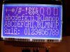
Whats happening here is sometimes it works as it should, correct numbers or letters in the correct palces, but more often than not i get a messed up display, numbers change to $$$$ signs and letters change to !;*($$£ signs.
Now just to make this even more wierd and annoying, if i change the PIC and put the same code onto it, (iv done this with 3 different PICs) the results differ each time, on PIC 1, the random symbols are in the place where the letters or numbers are, on PIC 2, there on different parts of the display, and on PIC 3, theres just a single pixel and a $ on the screen. All 3 PICS run the same code.
Iv tried this both on breadboard and on Professional PCBs, I know my hardware is correct as iv had this working perfectly in the past, but now it just refuses to work, iv even tried different LCDs but to no avail.
So, time for a new approach, it has been suggested that my code my be "buggy" and things are happening in the background at random, giving me this problem im having where sometimes it works but most of the time not.
So, has anyone ever used this type screen who could make me a sample piece of code to try that way i will know if its my code or something hardware related.
Im using a PIC18f26k20
Oh yeah, my current software uses the memory to store information and then updates the screen in one go, not sure if this would cause problems like this.
If anyone can help me out with this test software then i will send details of LCD pinouts.
Cheers
")