That's not a problem, it is
essential for how this setup works!
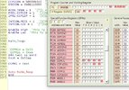
Look at the actual RC signal waveforms I posted earlier on:
View attachment 140109
The shift register moves a single bit through to each output in turn - like the "Channel x Servo signals"
The PPM waveform at the top is from the PIC compare hardware rather than a radio receiver, shifting the bit each 1 - 2 mS as appropriate for each respective servo position.
Unless the outputs changes
as the SR was clocked, there would not be any servo outputs!
For decades, Radio control receivers used to use a shift reg IC for the conversion back to servo pulses, before MCU based ones took over.
ps. If you need to translate to 5V power for the shift register, it should have been a 74HCT164
The HCT ones take TTL levels and 3.3V logic is perfect to feed those with the HCT device working on 5V.


")