Continue to Site

Welcome to our site!

Electro Tech is an online community (with over 170,000 members) who enjoy talking about and building electronic circuits, projects and gadgets. To participate you need to register. Registration is free. Click here to register now.

  • Welcome to our site! Electro Tech is an online community (with over 170,000 members) who enjoy talking about and building electronic circuits, projects and gadgets. To participate you need to register. Registration is free. Click here to register now.

Halloween costume ideas

Status
Not open for further replies.

MrDEB

Well-Known Member
On Oct 31st our small town of Ryderwood has a Halloween party (this is a 55+ city) and they have prizes for best costume.
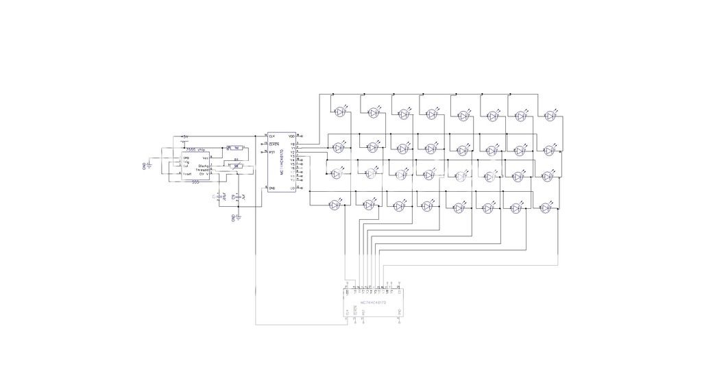
My idea for this year is a Cyborg. Using an old cpath mask w/ hose, put multi colored LEDs in hose and blue leds in mask. All controlled by a 4017 decade counter. Want to use a pic but time is not on my side. That's next year w/ LED matrix blinking eyes.
My plan is to use 8 opticoupliers driving 8 triacs. Yes I know I should use led driver chip and constant current chips as well but looking at putting the LEDs in series w/ about 8 per string (lots of load to drive. need to calculate current etc) looking at using several AAA or even D batteries. Thinking 12 volts might do it but ??
reason for using the opticouplier / triac combos is I found some left over SSR boards from my computer light display.
Now to locate the smd LEDs, small ribbon cable etc.
Any additional ideas are welcomed.
 
Draw a preliminary schematic. Then we can provide helpful feedback.

Having said this....................a Triac is the wrong power device to use in a battery powered project. As the optocouplers are too.
Use Mosfets instead.
 
I realize the triac and optocouplers are not really the best choice but it is what I have on hand. Want to keep parts to a minimum as well. I have several constant current chips as well as output led drivers but time and parts on hand are wanting to play. Reason for the triac etc. Looking at 5 leds per string and aprox 9-12 volt battery to be able to power the strings.
I would rather go with a pic but time to write a code etc. I have a working 555 / 4011 already from a different project. I even considered chariplexing the leds since each output is limited to say 20ma. Trying to balance the output with number of leds needed for effect.
This is a one time a year event for the electronics portion. KISS is in order IMO
working on a schematic
 
well got to rethink this project and think I came up with a different approach Using an LED matrix layout and two decade counters or one decade counter and one pic. Here is basically where I am headed. using a fast 555 timer speed the LEDs should appear to be all on.
halloween2_zpsjpd9ksc1.jpg

halloween2.jpg

halloween2_zpsjpd9ksc1.jpg
 
Last edited by a moderator:
If you want all the LEDs to appear on, why are you going to all that trouble?

Just connect all the LED+resistor pairs in parallel to a battery.

Maybe you need to rethink your schematic?
 
I agree dc and triacs are not really a good idea.
That said you could use them, the triac once turned on using dc would latch on, you'd need to remove power for them to unlatch, this can be done with a transistor if this kind of display would work for you, sort of a fill up then clear kind of thing.

There is or used to be a cmos chip that does what you indicate in that last drawing.
Dont forget to connect clk enable and reset on the 4017.
 
My favorite costume was a judges' black robes with with puffed shoulders and I went as a Priest with a magazine from Eric Idle called the Rutland Dirty Weekend Book and I made a brown paper cover and called it the Vatican Sex manual. The party was for a bunch of adults at my neighbour's who were mainly in Psychology University post grad training. What a hoot.

Talk about profiling.
 
Have revamped my plan as I located while sorting through all my electronic parts a bag of 50 tri colored leds common anode.
So am going with a better IMO plan implementing a pic since all projects are better using a pic.
need to draw up a new schematic using a Tap-28 board I ran across while sorting. plan to assemble a shield to solder the LED wires to (I have 6 wire leads so 6 cathodes and 18 anodes.
A transistor to switch the anodes off and on and ground all the cathodes. then to deal with the blue leds (3 sets of 3 in series) connected to two wires but needs 9v to light them up.
lots of little details.
This plan will require 6 transistors to control the anodes and rewire the blue leds to light up on 5 v.
schematic later tonight or tomorrow morning
and yes I could just connect everything to a battery but flashing leds would look better.
As an added addition to this costume, I ran across my bike turn signal prototype. Thinking using it as a necklace while it is powered up. Have the wireless remote attached to back of head for added decoration then tilting my head the large 5 x 7 matrix does it thing.
 
Status
Not open for further replies.

New Articles From Microcontroller Tips

Back
Top