Continue to Site

Welcome to our site!

Electro Tech is an online community (with over 170,000 members) who enjoy talking about and building electronic circuits, projects and gadgets. To participate you need to register. Registration is free. Click here to register now.

  • Welcome to our site! Electro Tech is an online community (with over 170,000 members) who enjoy talking about and building electronic circuits, projects and gadgets. To participate you need to register. Registration is free. Click here to register now.

Hair Straightener Stopped Working

Status
Not open for further replies.
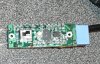
Hey guys. My friend (who also happens to be a girl) asked me to fix her straightener, which stopped working. When you turn the power switch on, the LED turns on, but very very dim, and the heating elements dont warm up.

I opened it up and checked all the usual things (burnt marks, components that look bad, etc) but didnt see anything out of the ordinary. Unfortunately I have no experience with the controller boards for hair straighteners, and Im sure that if I call up CHI (the maker of the iron), they wont give me the schematics.

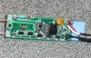
Has anyone had any experience repairing these things, or could possibly offer some insight as to how the controller board works? I have attached two photos of the board (front & back).

Any help or tips or things to check would be greatly appreciated!
 

Attachments

  • P1040804..JPG
    P1040804..JPG
    102.2 KB · Views: 2,967
  • P1040805..JPG
    P1040805..JPG
    110.1 KB · Views: 4,358
Last edited:
Well, a girlfriend asked me to fix her hair straightener too.

I think the control board is just a PWM circuit, driving a TRIAC

The internal wires are very cheap (specially the ones wired with the heating element). They tend to break when the jaw open or closes. Double check continuity.

I think that the heating element is somehow used to step down the voltage and feed the controller board, I don't know or if I'm wrong. Anyway, checking how many volts are feeding the circuit board and the TRIAC would be a good idea

PS: I wish you good luck reassembling it, the spring is a nightmare
PS2: Girls' hardware is damn complex and expensive! I remember that thing, it included LCD display and a microcontroller
 
Last edited:
Heh, the spring wasnt /that/ hard - there are little gaps where the CHI badge snaps in, that you can fit a screwdriver in to maneuver the spring. It also had a neat little oversized bushing that went inside the spring, to hold it in place while you reassemble the other side.

I checked continuity on the element that was next to the board, but not the one in the other half of the unit, so I will have to check that.

I agree with the PWM/TRIAC part, theres a single part in the middle (which Im in the process of removing all the #$*@'ing epoxy from) which looks to be the TRIAC, a little SOIC-8 part which Id assume is the controller, and a handful of transistors, with some diodes on the back (for rectification after the TRIAC). Hopefully Ill be able to piece together a schematic over the weekend, that should help a lot too.
 
I've never repaired a hair straightener before but I think it's possible that if the triac fails it will conduct continuously causing the themal fuse to blow, so I suggest you test them both and replace if needed.
 
My only concern with that idea is the current from a modern DVM might be too low to keep an SCR or TRIAC conducting.

I like using an LED with a suitable series resistor, a DC power supply and a suitable gate resistor.
 
I do believe it's a thermal fuse, but I tried testing it in-circuit (dont have my soldering equipment with me here, hence waiting till I get home) and it read ~2 ohms, so I assumed it was fine. I plan to properly test it when I have the tools to desolder one leg.
 
I've never had any luck desoldering or soldering thermal fuses, I just cut the legs of and use crimps to connect them instead of soldering.
 
If SCR is OK, there are three options left:
1) Check the heating element directly
2) Give your girlfriend a new hair straightener, as a present
3) Convince her that the curls look great (even if they don't) :)
 
Just tested the two elements, both came up as 83 ohms. Also lifted one leg of the fuse and it tests fine. Unfortunately, the straightener costs well over $200+tax, so Im going to pull and test pretty much every component before I deem a new one necessary ;) Totally with you on #3

EDIT put the SCR back and powered up the board, I have 120v after the fuse, but 0.0v on the heating elements. Im beginning to think the unknown IC on the top is a controller thats gone, because none of the components have voltage across them
 
Last edited:
ok I think you need to follow things on a logical level here. which side is 'after the fuse' and where does it go? Have you looked at the switch? Also what are the two black wires near the mains input? Are they a second coil and are they in series with the first?
 
Last edited:
After the fuse implies the electricity has flown through the fuse, from the input, and then goes wherever else it needs to go. After the fuse just meant that the fuse was passing current.

The two black wires near the mains input are the wires that go to the other heating element.

The switch was removed and tested, and works fine.

The IC on the board is labelled:
2903
4095U
JRC

and it is an SOIC-8 package

The heating elements are wired in parallel, with the -ve being fed by the AC cold wire, and the +ve being fed by the diode array on the back.

EDIT I think Ive found the datasheet:
**broken link removed**

However, I was hoping the datasheet would give the markings found on the chip, but it doesnt, so all Ive got to go by are 2093 and JRC (Japan Radio Company).
 
Last edited:
It you manage to trace the whole circuit, you might be able to figure out what that IC is.

If you post the circuit with a box for the unknown IC, we might be able to help you find out what it is.
 
tried NTE site for the number. looks like a comparator
Semiconductor Cross Reference Search Results


acThe IC on the board is labelled:
2903
4095U
JRC

and it is an SOIC-8 package


EDIT I think Ive found the datasheet:
**broken link removed**

However, I was hoping the datasheet would give the markings found on the chip, but it doesnt, so all Ive got to go by are 2093 and JRC (Japan Radio Company).[/QUOTE]
 
Im almost done drawing the schematic - should have it posted tonight.

While Im at it, is there a common opamp (like a TL072 or similar) that I can use in place of the NTE one, to rule it out?

EDIT or whats the easiest way to test an op-amp?
 
Last edited:
Status
Not open for further replies.

Latest threads

New Articles From Microcontroller Tips

Back
Top