Continue to Site

Welcome to our site!

Electro Tech is an online community (with over 170,000 members) who enjoy talking about and building electronic circuits, projects and gadgets. To participate you need to register. Registration is free. Click here to register now.

  • Welcome to our site! Electro Tech is an online community (with over 170,000 members) who enjoy talking about and building electronic circuits, projects and gadgets. To participate you need to register. Registration is free. Click here to register now.

membrane touch pad not working on 1 function

puckhead

New Member
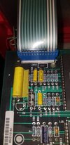
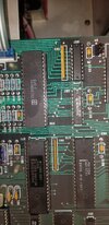
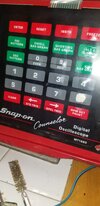
this is a touch pad from an early 90s snap on automotive scope. the problem is button #8 doesnt work. the connector to the board is 13 pin. looking at the pic, the second from the left is ground. the next 8 dark green lines are buttons 1-8. all the green lines are high ( 5V) and each goes low when you press the switch for the line. they dont go completely low, they drop to around 1.5V. the white lines are low, and go high when you press the non numeral buttons. the 1-8 numerals correspond to numbering the cylinders of a car. if it asks how many cylinders, buttons 1-7 will each show on the screen. 8 does nothing. when i press 8 , the line for 8 stays high. bad button? not sure. if i ground the line for 8 and pull the line low, i dont get an 8, i get a reset, but like i said, working buttons drop to 1.5v . maybe i need something in line to prevent the line for 8 to drop to zero when i manually ground it? somehow keep it at 1.5v when pulled low? i dont really know how the pad works. i will never get a schematic for this, snap on keeps everything under wraps. 24 buttons, with 13 pins on the connector. i guess some kind of matrix, but im familiar with strobes on one side, and returns high. 4 strobes, 4 returns 16 possible switches. not sure how they get 24 out of 13 pins. i lifted the membrane on a good switch, and touching it with a small brass conductive bristle brush makes the switch work, as does pressing the membrane. i removed button 8 membrane, and the bristle brush doesnt pull the line low. again, touching that line for button 8 to ground, pulling it low, doesnt register an 8, it registers a reset. if i knew how it worked, i could possibly put in a momentary switch to use as button 8. ps- the button 8 was probably used more than the others, a lot of 8 cylinder cars back then. other than the first green line( pin 2 ) going to ground, all the other pins go through a pull up resistor to a 74ls245n . i tried a different 74ls245n, no joy. hope this makes sense, ive hit a wall. i am in no way an electrical engineer or wiz, im more like a very good plumber for electrons. anyway, thanks to all
 

Attachments

  • 20240906_194259.jpg
    20240906_194259.jpg
    1.1 MB · Views: 76
  • 20240906_194327.jpg
    20240906_194327.jpg
    1.6 MB · Views: 76
  • 20240906_195230.jpg
    20240906_195230.jpg
    1,000.5 KB · Views: 84
Membrane keypads such as that are arranged in some form of matrix or grid.

There may be some dedicated connections to specific buttons, but most will be cross connecting two of the points on the connector.

In its simplest grid form, something like this, with each button connecting between a row and a column.

images


The microcontroller (in that example) pulls one row wire low at a time & reads the column signals, to see if any switched in that row are then low (pressed).

If a column wire was low all the time, it reads as all the switches in that column pressed, which is invalid - it only reads if just one is pressed.

The keyboard itself will be two plastic sheets printed with conductive ink, and a thin spacer between them. Pressing a key shorts a point on one layer to a point on the other. Some also have a metal dome in the space to give a tactile click when the key is pressed.

IMG_0434-1.jpg


They are generally not directly repairable.

I've repaired equipment that had membrane keyboards by replacing them with an array of 6x6mm low profile buttons on stripboard, with a hole for each button through the panel & with just the front layer of the old membrane re-attached to the front.

With the correct spacing to the switches, they work just like the original membrane contacts did & look no different at all.

You do need to work out the switch matrix wiring, though, and duplicate that with the connections to the new buttons.
 
When you say that when a button is pressed a line goes from 5 volts down to 1.5 volts. Is this measuring it with a meter or an oscilloscope ? If is was with a meter it may be going close to zero for part of the scanning squence.
If the electrical matrix was was the same as the physical matrix it would only require 10 wires. 4 for columns and 6 for rows.

Les.
 
True membrane switches with (air bubbles /blisters) are likely to drop to only 1.5v because the circuit is printed with fairly high resistance silver ink. Used in the very inexpensive and high volume keyboards sold by Dell, for example.

The switches shown in post #2 are not membrane switches but commonly mistaken for membrane switches - those are snap or tactile switches and require some stamped metal plate made of spring steel to be soldered over it. Like this...


I doubt there is any problem with grounding the switch with a "manual" connection. Most likely, your switches have some corrosion from the air in the repair shop environment (especially if there are any diesel emissions and sulfur oxide gasses.

You can pull the board, measure the tactile switches, remove them. Polish them with a soft white pencil eraser. Solder them back on. If they are damaged ( commonly cracked) or it could be a broken solder joint to the sprung steel. Easy fix either way.
 
Last edited:
When you say that when a button is pressed a line goes from 5 volts down to 1.5 volts. Is this measuring it with a meter or an oscilloscope ? If is was with a meter it may be going close to zero for part of the scanning squence.
If the electrical matrix was was the same as the physical matrix it would only require 10 wires. 4 for columns and 6 for rows.

Les.
the 1.5 v is measured with both a scope and a fluke meter.
 
The switches shown in post #2 are not membrane switches
You mean the keyboard with the two layer membrane tail in the first photo??
The tactile domes you link to are for placement in a key panel. The data sheet says "Not to be soldered".

Tactile domes with membrane keyboards are quite common.

Reliaswitch+tactile+membrane+switch.jpg


I doubt there is any problem with grounding the switch with a "manual" connection.
There are 24 buttons in the keypad - but only 13 contacts on the connector.
Not possible without some multiplexing??
 
Sounds like button #8 might be the issue here. If grounding the line results in a reset instead of registering an 8, it’s probably a connection or button problem. I’d suggest adding a pull-down resistor, like a 10kΩ one, to the line for button #8. This might help stabilize the voltage drop when the button is pressed.

I had a similar problem with an old piece of equipment once, and adding a pull-down resistor helped fix the erratic behavior. If that doesn’t work, you might need to look into replacing the button or checking the membrane connections.
 
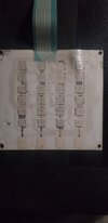
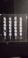
Further investigation shows it to be the pad itself. I noticed some of the other digits were hit and miss whether they worked or not. I was able to get positive results jumping the connector pins with. The three in one color lines in the previous pics are 3 strobe lines. The next 8 lighter lines are switches 1-8. Then there are 2 more. One is ground, not sure of the other. I am now posting 3 more pics. I was able with freeze spray to break the glue bond, and can see the matrix. I am going to build a panel with monitor push buttons. Looking at the matrix, I already have a headache but seeing it is a real head start. Will I need to use diodes to isolate the switches? Obviously no diodes on the skin in the pics. I'll probably go half insane transferring what I see to a schematic for my new board. Anybody who can work it out from the pic and draw it would be a great help. im curious about the 4 squares at the bottom, and their purpose. You can see on the push side( the clear side) the columns go all the way to those square pads, but it looks like for no reason. Any and all thoughts are welcome and appreciated. Thanks
 

Attachments

  • 20240909_153413.jpg
    20240909_153413.jpg
    1,004.5 KB · Views: 74
  • 20240909_155517.jpg
    20240909_155517.jpg
    895.4 KB · Views: 78
  • 20240909_155523.jpg
    20240909_155523.jpg
    1.2 MB · Views: 69
Looking at the pictures in your post #8 it looks like the the keypad consists of two layers. the right hand picture shows one axis of the matrix (4 columns) I assume that this is the underside of the left hand picture. I think you will find that the signals on the the 4 columns are the scanning pulsed for one axis of the matrix. I think the signal on each column will have a 25% duty cycle and if you have a 4 channel scope you will find the pulses are scanning the columns in sequence. I think the the black spot on the next to bottom button on the left hand column is where the conductive coating is warn away. You may be able to get some conductive paint to repair it. There are two basic types. One uses metal particals and has quite a low resistance. The other uses graphite particals and has quite a high resistance. (This type is sold for TV remote control repair.) Both types are sold on ebay. You could also trace out the matrux and make a new keypad using tactile push button switches.

Les.
 
im going to go with making a panel using push switches. will i need isolation diodes between the switches? thanks
 
As there are no diodes on the existing panel I don't see any reason why they would be required with push buttons.
I suggest that you start by tracing out the schematic of the existing panel. If you post the schematic we will be able to better understand exactly how it works.

Les.
 
i agree, probably no diodes. i wish i had a schematic. the manufacturer hangs on to them like grim death, or the formula for coca cola. have to work it out by hand. thanks
 
It looks quite difficult to follow the tracks so I would start working it out from continuity tests.
Give the rows numbrs. Say 1 to 6.
Give the colums letters. Say A to D
Give the connections on the plug numbers. Say 1 to 9.
Start with one meter lead connected to the plug pin 1. Then make a list of all the key positions that show continuity to that pin on the plug. Repeat this on each of the 9 pins on the plug. I suspect that all the the key positions from each connector pin will be on the same row.
Using an excel spreadsheet may be the easiest way to document the test results.

Les.
 

Latest threads

New Articles From Microcontroller Tips

Back
Top