Electro Tech is an online community (with over 170,000 members) who enjoy talking about and building electronic circuits, projects and gadgets. To participate you need to register. Registration is free. Click here to register now.
Welcome to our site! Electro Tech is an online community (with over 170,000 members) who enjoy talking about and building electronic circuits, projects and gadgets. To participate you need to register. Registration is free. Click here to register now.
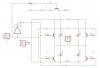
HMM... Can i simply use a inverter to connect A and B and use another transistor to enable and disable the inverter hence making this 2 wires only with no possible chance of putting both HIGH ?
HMM... Can i simply use a inverter to connect A and B and use another transistor to enable and disable the inverter hence making this 2 wires only with no possible chance of putting both HIGH ?
Rather than enable/disable the inverter, leave it connected, and use the transistor (between ground and your h-bridge) to switch power to the entire h-bridge; you won't gain back EM braking (it will still be "freewheel"), but maybe with some extra logic (perhaps instead of the transistor switching power, or maybe in addition). Ultimately that will depend on whether braking is important to you.
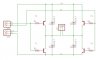
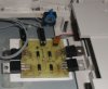
Ok im about to make a PCB without the INVERTER ... i dont have heatsinks but i do have a nice small fan from a old laptop cpu. You think that would be good enough ?
wow doesnt work. Did you people notice it was a PNP and NPN so if i supply power only one will work. So my original schematic would have worked. Probably only needed resistors
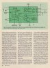
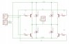
Hey Jason, this is a link to pretty much what you want, it actually uses the mentioned transistors (2N2907 and 2N2222 versions). Either Q1 and Q4 are on, Q2 and Q3 are on or both are off. At no time can all be on which as covered results in a dead short and things get ugly. Give the link a read and look it over, it should be pretty much what you have.
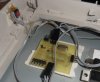
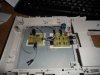
ok my version works well!! yay its alive!!!. Basically i saw a video on using a old cdrom as a base for making a agitator for etching pcbs so it opens and closes automatically. I finally written entire code and test and works like a charm!!!
This site uses cookies to help personalise content, tailor your experience and to keep you logged in if you register.
By continuing to use this site, you are consenting to our use of cookies.