Electro Tech is an online community (with over 170,000 members) who enjoy talking about and building electronic circuits, projects and gadgets. To participate you need to register. Registration is free. Click here to register now.
Welcome to our site! Electro Tech is an online community (with over 170,000 members) who enjoy talking about and building electronic circuits, projects and gadgets. To participate you need to register. Registration is free. Click here to register now.
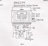
You might want to find out what the current needs of the motor are, before you order the L293; if it needs more than 600 mA, verify with L293 you are getting (one allows for only 600 mA of current, but a different version goes up to around 1 A - note you will have to provide a heat sink). Another thing is that it is possible to stack L293s (I've only heard of doubling them up - I doubt you can go beyond that, and even doubling them up sounds iffy to me, since the outputs are transistors, not fets - but there's anecdotal evidence that it works). I doubt the motor will require it, but the L298 is the next level up (well, for these old-school h-bridges) for current rating; they'll take you up to around 4 A in bridged mode (there are two 2 A bridges on each IC), but you will need a heat sink, once again (multiwatt-15 heat sinks aren't easy to find, btw). Also, they require a special pad layout (it's not a standard 0.1 inch grid), so prototyping with them isn't easy (I've used this guy's adaptors with success, though: https://www.jrhackett.net/L298adapter.shtml). Another interesting option for low-current h-bridges are these small SIP devices (Rohm BA6886N): **broken link removed**
i used an opticoupler from four pic pins. used a 330ohm res on the bases of 2n2222/2n2907 (with pulup/puldwn res ), i also used shotkey diodes from gnd=motorout=pos. the motor i used is from the same as your project , it powered by 3.6v and has a stall of about 100ma.
Jason, what are R1 and R2 for? What voltage are you applying to the bases (A&B)?
I have one of those little motors lying here so just for the hell of it I ran it off a 12 volt battery (12.7 volts). Free running under no load it only draws about 35 mA and in a dead stall it gets up to about 800 to 900 mA. If you have a 2N2222 (NPN) and 2n2907 (PNP) they would likely work and I would use maybe 1 K base resistors to start if you are applying about 5 volts to the bases.
What you have is substantial overkill for what these little motors need.
<EDIT> I see Joe G posted, you had a much lower stall current than I got but yeah, I agree on the transistors. </EDIT>
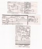
First off - you need base resistors on all the transistors - start with 1K resistors, that should be OK (there are ways to calculate what you need). You'll also want to add your diodes back in for back-EMF.
Now - you want to connect "A" to the upper-left PNP and the lower-right NPN, and "B" to the upper-right PNP and lower-left NPN. The way you have it set up, current won't flow thru the motor (and instead is shorting thru the transistors - which is BAD and called "shoot-thru") when activating A or B. You will also want to increase the voltage of the motor power source, as each transistor is dropping about a volt (leaving you with only 3 volts to go thru the motor - which is OK if the motor is a 3 volt motor, otherwise not).
Finally - depending on the current needs of the motor (not high likely) - you may need small heatsinks on the transistors (but I doubt it - those transistors are waaaay overkill for a small motor like you have)...
This site uses cookies to help personalise content, tailor your experience and to keep you logged in if you register.
By continuing to use this site, you are consenting to our use of cookies.

")