Continue to Site

Welcome to our site!

Electro Tech is an online community (with over 170,000 members) who enjoy talking about and building electronic circuits, projects and gadgets. To participate you need to register. Registration is free. Click here to register now.

  • Welcome to our site! Electro Tech is an online community (with over 170,000 members) who enjoy talking about and building electronic circuits, projects and gadgets. To participate you need to register. Registration is free. Click here to register now.

h bridge problem

Status
Not open for further replies.

bananasiong

New Member
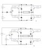
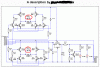
i've found a h bridge circuit. i need to supply 12V to the motor, and my signal can only be 5V. when the signal supply to a, the motor goes forward, when the signal supply to b, it goes reverse. i've tried both the circuits A and B. it gives only 5.xxV output. but when i change the signal to 12V, it gives a 11.xx v output. can anyone help me??
i need to control it with only 5V signal to move the motor in both direction in 12V.
thanks for helping.
 

Attachments

  • 2_706.jpg
    2_706.jpg
    37.4 KB · Views: 1,122
Well you need to supply 12V to A and B otherwise the top switches wont switch (I am supprised they are!!!! esp since the emitter will be jumping)


If you want to control from 5V you will need another BJT that takes in 5V to turn-on, but the Collector (via a resistor) is tied to 12V, the collector connection (which will now toggle between 12V and ~0.6V) can now be tied to the point you want to control
 
Styx said:
Well you need to supply 12V to A and B otherwise the top switches wont switch (I am supprised they are!!!! esp since the emitter will be jumping)


If you want to control from 5V you will need another BJT that takes in 5V to turn-on, but the Collector (via a resistor) is tied to 12V, the collector connection (which will now toggle between 12V and ~0.6V) can now be tied to the point you want to control

?? i don't really get what u mean..?? how to use another bjt to turn it on?? can u show me the circuit construction??
 
phalanx said:
bananasiong said:
anyone can solve my h-bridge problem??

Did you miss Nigel's last post?

i couldn't find the transistor at my place from Nigel's circuit. and.. he said that the circuit design is poor.. but do u know that, i pick it from the bonzana's book? try to respect others.
 
bananasiong said:
phalanx said:
bananasiong said:
anyone can solve my h-bridge problem??

Did you miss Nigel's last post?

i couldn't find the transistor at my place from Nigel's circuit. and.. he said that the circuit design is poor.. but do u know that, i pick it from the bonzana's book? try to respect others.

I don't know Mr. Bonzana but now that you know his circuit does not work off a 5V signal, maybe you should try googling for alternate H-bridge designs that do.

Here are a few I have found (taking from the first page of a google search).

http://www.mcmanis.com/chuck/Robotics/tutorial/h-bridge/bjt-circuit.html
**broken link removed**
 
bananasiong said:
but do u know that, i pick it from the bonzana's book? try to respect others.

Just because it was in a book doesn't mean it's any good!, and it's still a VERY poor circuit, and doesn't deserve any respect!.

The example I gave the link to is from a magazine robot called Cybot, it's not intended to be copied 'as is' but as an example of how an H-bridge works. I wouldn't say it's a great example, but it is considerably better than the NPN only example!.
 
Nigel Goodwin said:
bananasiong said:
but do u know that, i pick it from the bonzana's book? try to respect others.

Just because it was in a book doesn't mean it's any good!, and it's still a VERY poor circuit, and doesn't deserve any respect!.

The example I gave the link to is from a magazine robot called Cybot, it's not intended to be copied 'as is' but as an example of how an H-bridge works. I wouldn't say it's a great example, but it is considerably better than the NPN only example!.

okay... but i can't get the transistor in my place.. do u have other circuits?? thanks..
 
bananasiong said:
Nigel Goodwin said:
bananasiong said:
but do u know that, i pick it from the bonzana's book? try to respect others.

Just because it was in a book doesn't mean it's any good!, and it's still a VERY poor circuit, and doesn't deserve any respect!.

The example I gave the link to is from a magazine robot called Cybot, it's not intended to be copied 'as is' but as an example of how an H-bridge works. I wouldn't say it's a great example, but it is considerably better than the NPN only example!.

okay... but i can't get the transistor in my place.. do u have other circuits?? thanks..

You don't need the specific transistors, use what's available, bearing in mind the current requirements of your motors.
 
Nigel Goodwin said:
Just because it was in a book doesn't mean it's any good!, and it's still a VERY poor circuit, and doesn't deserve any respect!.

Using polarised capacitor across the motor terminals does not deserve any respect either. :twisted:
 

Attachments

  • bad_circuit.gif
    bad_circuit.gif
    19.5 KB · Views: 750
eblc1388 said:
Nigel Goodwin said:
Just because it was in a book doesn't mean it's any good!, and it's still a VERY poor circuit, and doesn't deserve any respect!.

Using polarised capacitor across the motor terminals does not deserve any respect either. :twisted:

You will notice I pointed that out in my explanation of the circuit! :roll:
 
akg said:
bananasiong said:
if other transistor can be used.. then what is the transistor?? please help.. thanks!!
say 3055(npn) and 2955 (pnp)
or bd140 and bd139
then what about the transistor to switch both pnp and npn? i mean the npn transistor which the collector connected to the base of pnp and the emitter connected to the base of npn.
 
Its not as bad as your useless reply... Ive had the circuit driving 6 amp motors controlled with a BASIC stamp for 3 years with no problems.
 
Status
Not open for further replies.

Latest threads

New Articles From Microcontroller Tips

Back
Top