Electro Tech is an online community (with over 170,000 members) who enjoy talking about and building electronic circuits, projects and gadgets. To participate you need to register. Registration is free. Click here to register now.
Welcome to our site! Electro Tech is an online community (with over 170,000 members) who enjoy talking about and building electronic circuits, projects and gadgets. To participate you need to register. Registration is free. Click here to register now.
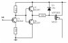
The lower gate drivers (T3/T4) are connected to +12V, the VMOTOR is 24V.
I try this design in order to avoid use of dedicated mosfet drivers like HIP4081 or IR2112, they are difficult to find and little bit expensive for my pocket.
I think that Styx have found the problem, the upper mosfet do not switch correctly and also is very slow , so I revise my design.
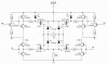
As drawn in your original schematic, the lower gates will only go to about 4.3V, and that transition will be slow due to the series 10k resistor. Have you changed the design?
The IRFZ44N is not even guaranteed to be on at 3.6V. The one you have may be on, but MOSFETs' threshold voltages vary widely, even for different units of the same part number. You need to consult the datasheet if you want to make a design that will work reliably with any given part. Vgs(to)=4V max, and that's at only 1ma!. Rds(on) is specified at Vgs=10V.
The diodes are used to reduce or eliminate crossover distortion in linear audio amplifiers.
This circuit never operates in a linear mode, it switches, so the diodes aren't necessary. This circuit uses pulse-width-modulation at a very high frequency to control the speed of its motor.
Since this circuit switches full-power pulses from the power supply with changing pulse-widths to control the motor's speed, an important design concern is "shoot-through" where both the upper and lower transistors might conduct a massive current through each other if their pulses overlap.
This site uses cookies to help personalise content, tailor your experience and to keep you logged in if you register.
By continuing to use this site, you are consenting to our use of cookies.