Electro Tech is an online community (with over 170,000 members) who enjoy talking about and building electronic circuits, projects and gadgets. To participate you need to register. Registration is free. Click here to register now.
Welcome to our site! Electro Tech is an online community (with over 170,000 members) who enjoy talking about and building electronic circuits, projects and gadgets. To participate you need to register. Registration is free. Click here to register now.
Hey all,
I have built a stepper motor driver using PIC PWM to control current but the bridge low side is hot while the high side is cold.
Can someone help me ??
First you need to clarify what you are trying to do?, you specify "stepper motor", then proceed to show a driver for a DC motor - so which are you trying to do?.
As PWM is used to vary the speed of a DC motor, it's not very relevent to steppers either?.
I try to clarify,
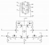
the schema refer to one motor windings, the motor is bipolar and I use PWM to control the current through the motor winding.
Practically the PIC changes the duty cycle to that required to maintain the current.
I hope to have explained clearly :cry:
OK, although I don't really see the need for PWM? - but regardless, the H-bridge looks fine - although it's ABSOLUTELY CRUCIAL that you don't accidently turn both PIC outputs HIGH at the same time!.
I had a second look at your schematic and I now understand its operation. The problem I have with it is that on power up, the PIC I/O ports are in the input state. There is a delay where the PIC has not yet been initialized and the inputs to the 7408 TTL gates are floating. This could turn the output HIGH and will cause all 4 FETs to conduct.
OK, although I don't really see the need for PWM? - but regardless, the H-bridge looks fine - although it's ABSOLUTELY CRUCIAL that you don't accidently turn both PIC outputs HIGH at the same time!.
Do you think that chopper works better than PWM ?
Before changing direction I set pin to low, after that I change the duty cycle for the next step and finally I set pin for new direction.
I have forgotten something ?
I just don't see why you need to do anything? - a stepper moves a single step (or a half step) at a time, reducing the power to the motor can either move exactly the same step, or be too low to move at all. So I don't see the advantage of lowering the power available?.
I just don't see why you need to do anything? - a stepper moves a single step (or a half step) at a time, reducing the power to the motor can either move exactly the same step, or be too low to move at all. So I don't see the advantage of lowering the power available?.
There is good reason to run a stepping motor at a supply voltage above that needed to push the maximum rated current through the motor windings. Running a motor at higher voltages leads to a faster rise in the current through the windings when they are turned on, and this, in turn, leads to a higher cutoff speed for the motor and higher torques at speeds above the cutoff.
Microstepping, where the control system positions the motor rotor between half steps, also requires external current limiting circuitry. For example, to position the rotor 1/4 of the way from one step to another, it might be necessary to run one motor winding at full current while the other is run at approximately 1/3 of that current.
MTP2955:
Designed for low voltage, high
speed switching applications in power supplies, converters and power
motor controls, these devices are particularly well suited for bridge
circuits where diode speed and commutating safe operating areas are
critical and offer additional safety margin against unexpected voltage
transients.
• Avalanche Energy Specified
• IDSS and VDS(on) Specified at Elevated Temperature
IRFZ44N
Advanced HEXFET® Power MOSFETs from International
Rectifier utilize advanced processing techniques to achieve
extremely low on-resistance per silicon area. This benefit,
combined with the fast switching speed and ruggedized
device design that HEXFET power MOSFETs are well
known for, provides the designer with an extremely efficient
and reliable device for use in a wide variety of applications.
You are driving the lower gates with emitter followers, so the gate drive will be 0.7V lower than the output voltage from your PIC. This may be too low to get good on resistance. The slow gate drive risetime also contributes to heating.
What voltage is VMOTOR? This will help
I am suspecting that when you are ment to be actually turning OFF the upper FET's, the gate potential still has enough for conduction to occur, be it very slightly it is still an ACTIVE-region current and very lossy
The GATE of the top FET's need to be pulled upto VMOTOR to turn them off
Equally why have you gone to all the effort of providing different charging resistors (for ON and OFF) for the lower FET's and NOT the upper FET's
The imballance in switching times is going to give you switching shoot-throughs if you are not careful
What voltage is VMOTOR? This will help
I am suspecting that when you are ment to be actually turning OFF the upper FET's, the gate potential still has enough for conduction to occur, be it very slightly it is still an ACTIVE-region current and very lossy
The GATE of the top FET's need to be pulled upto VMOTOR to turn them off
Because the NPN need's to be turned-ON for the top FET to turn-OFF.
The Top-FET is a P-Type.
Without knowing what the VMOTOR is w.r.t. that Zener then dunno what is happening, might be nothing, but for just the TOP-FET's to be getting warm means they are drawing more current then they should be.
When the top-FET's turn-ON they will be saturated (just like when the bottom FET's turn-ON), thus the only time that ONLY the top-FET's can be dissipating more power is if they are not really OFF
You are driving the lower gates with emitter followers, so the gate drive will be 0.7V lower than the output voltage from your PIC. This may be too low to get good on resistance. The slow gate drive risetime also contributes to heating.
I agree. I checked the IRFZ44N and it needs a voltage higher than 5.0V to get low ON resistance.
I would suggest to try to use H-bridge drivers like the Intersil HIP4081 or a pair of the half bridge drivers from IRF. You can then use N channel FETs on both the high and low sides.
What voltage is VMOTOR? This will help
I am suspecting that when you are ment to be actually turning OFF the upper FET's, the gate potential still has enough for conduction to occur, be it very slightly it is still an ACTIVE-region current and very lossy
The GATE of the top FET's need to be pulled upto VMOTOR to turn them off
Because the NPN need's to be turned-ON for the top FET to turn-OFF.
The Top-FET is a P-Type.
Without knowing what the VMOTOR is w.r.t. that Zener then dunno what is happening, might be nothing, but for just the TOP-FET's to be getting warm means they are drawing more current then they should be.
When the top-FET's turn-ON they will be saturated (just like when the bottom FET's turn-ON), thus the only time that ONLY the top-FET's can be dissipating more power is if they are not really OFF
Styx, you need a nap. :shock:
The top FETs are indeed P-channel,and the gates need to return to VMOTOR for them to turn off, which they will indeed do when the NPNs turn off (not ON, as you said above). The zeners are there to limit the source-to gate voltage to Vzener if VMOTOR is high enough for the zeners to conduct when the NPNs are on.
Besides, our OP said the bottom trannies were getting hot, not the top ones.
This site uses cookies to help personalise content, tailor your experience and to keep you logged in if you register.
By continuing to use this site, you are consenting to our use of cookies.

")