Electro Tech is an online community (with over 170,000 members) who enjoy talking about and building electronic circuits, projects and gadgets. To participate you need to register. Registration is free. Click here to register now.
Welcome to our site! Electro Tech is an online community (with over 170,000 members) who enjoy talking about and building electronic circuits, projects and gadgets. To participate you need to register. Registration is free. Click here to register now.
I think that is the cause of the problem too but my circuit suppose to drive upper side high and lower side low at the same time. They shouldn't be driving high at the same time.
i want to know if there is any difference between driving h bridge with 2 pwm and driving with one. i want to do position control but it seems not working well.
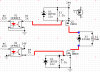
The Circuit below(Courtesy of SgtWookie) works just fine with the exception of the detail that the Pmosfet(an IRF 9540N) overheats excessively after about only 1 second of usage!
The 2k resistors have such a high value that the Mosfets turn on and off slowly which causes them to get hot when PWM is used.
The opto-couplers might not be able to provide enough current for lower value resistors.
Each Mosfet can dissipate 100W if a huge heatsink is used.
Hi audioguru,
Thanks for your response.
Actually the only Fet that over heats is the PMos one and only if it is kept opened for longer than 1 second and, BTW, I am not using PWM with these. I guess the positive current at 24v and 2.5 Amps. is just too much but then there must be a way too. As for the 2k R's what is your suggestion then?
You forgot to look at the datasheet for the 4N25 opto-isolator. Its minimum transfer ratio is only 20%. So when the emitter has 5.8mA then the opto-transistor conducts a minimum of only 1.2mA and the gate-source of the P-channel Mosfet gets only 6.4V instead of 10V.
Use a 4N35 opto-isolator that has a minimum transfer ratio of 100%.
Being a NewBie I make a lot of mistakes amongst which to mention that I am actually using PC817 with 50%Current transfer ratio ( CTR: MIN. 50% at I F = 5mA ,VCE=5V).
Is that sufficient or not please?
Also please note some data below to help with the troubleshooting:
Your Mosfet should have 10V between its gate and source to turn on completely. Yours has only 9V but it is OK.
Your Mosfet should turn on pretty well and not get hot with a current of only 2.5A.
Maybe you are not using the Mosfet part number shown in your schematic?
Thank you for your response. Actually you are quite right and after rewiring it the heating has decreased a lot and I think it may have been due to my having connected the Solenoid's Diode the wrong way round?!
I will next connect a heat sink to it and at then the heating should become quite tolerable for my use.
BTW, how did you calculate the 9 volts between the gate and the source? Based on my numbers above it seems to be 5 volts or not?
If so how can I remedy that?
Actually you are quite right and after rewiring it the heating has decreased a lot and I think it may have been due to my having connected the Solenoid's Diode the wrong way round?!
The source is at +24V and the gate when the Mosfet was loaded was at +15V. But the drain was at +1.1V instead of very close to +24V so the backwards diode was shorting the load.
Thank you for the explanation. There definitely was a short(since Power Supply LED was also dimming under load!) although it's source not yet quite known to me since the Sol. was also operating!
Is there an easy way to calculate what the voltages should be at G,D, & S?
Presently they are, Pmos Loaded & Opto ON:
Source* Drain* Gate
20* 17* 15.6
Well, did some more tests and foun that the heating problem is associated with the type of solenoid I use. The one that was not heating too much as reported above was a Sol. that was wound with a 0.35 mm wire and the one overheating is a same size Sol. but wound with 0.5 mm wire!
How can possibly the thickness of the wire be related to the problem?
Below the data on the .5mm Sol., Pmos Loaded & Opto ON:
Source* Drain* Gate
19* 3* 15
As can be noted, the wire thickness drastically affects the Drain voltage!!!?
Don't you know that short thick wire on a coil draws much more current than long thinner wire on the same coil?
Simply measure the resistance of each coil then use Ohm's Law (the voltage across it) to calculate the current.
I notice that your 24V power supply has its voltage sag when the solenoids are turned on.
On your last measurement the gate to source voltage is only 4V instead of the needed 10V so the Mosfet can barely turn on enough and has 16V across itself.
Obviously the thicker wire draws more current but even that should have been within the limits of the Fet! However this has led me to check for shortage within the Sol. itself and indeed the .5mm wire coil had a short with it's Aluminium core...which explains the heavy draw and the Power supply sag. A good warning to switch to plastic cores for future.
Thanks for your help though.
This site uses cookies to help personalise content, tailor your experience and to keep you logged in if you register.
By continuing to use this site, you are consenting to our use of cookies.