Continue to Site

Welcome to our site!

Electro Tech is an online community (with over 170,000 members) who enjoy talking about and building electronic circuits, projects and gadgets. To participate you need to register. Registration is free. Click here to register now.

  • Welcome to our site! Electro Tech is an online community (with over 170,000 members) who enjoy talking about and building electronic circuits, projects and gadgets. To participate you need to register. Registration is free. Click here to register now.

H-bridge mosfet overheat and l298 pwm problem

Status
Not open for further replies.

ericchee

New Member
I have been dealing with l298 and mosfet driver lately and something happen which i do not understand.

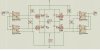
MOSFETs that i am using are ifr9510 for upper bridge and irfz34 for lower bridge(all four are heat sink eqipped). I know the irf9510 commonly is paired with irf510. Since only irfz34 available to me, i used it for testing. My question is whether this kind of pairing will generated lots of heat. I could smell something if i put my nose nearer( not burn smell) and the driver is working(even can control the speed of the motor). However, i dare not to drive the motor too long. the MOSFETs are isolated by optocouplers 4n35. I'm not sure if this has anything to do with the overheating but i remember someone said that optocoupler cannot support the high speed of the PWM.

For l298, i am getting a insensitive speed control. l298 is controlled by PIC16F877a. the speed is set at range of 0 - 128(0 for 0% duty cycle and 128 for 100% duty cycle).

Direction = anticlockwise
Max speed = 0
Min speed = 128

Direction = clockwise
Max speed = 128
Min speed = 0

Above are results i suppose to get but what i got are:

Direction = anticlockwise
Max speed = 0
Min speed = around 30 - 40 ( >40 the motor completely off)

Direction = clockwise
Max speed = around 30 - 40 (>40 motor complety on / full speed)
Min speed = 0

i know it's hard without schematic but i'm in rush now. I'll post the schematic later. Hopefully, anyone can provide me some advices and assistance in the mean time. TQ

Eric
 
Last edited:
here's the circuit. for the mosfet driver, the lower mosfet is irfz34. one things different between the schematic and my test circuit is that i did not have diodes. i'll include it in future. DIRECTION is set to PIC normal pin(set either high or low) and PWM is set to PIC PWM pin.
 

Attachments

  • Mosfet.JPG
    Mosfet.JPG
    115 KB · Views: 3,831
  • l298.JPG
    l298.JPG
    104.9 KB · Views: 1,766
You forgot to tell us the frequency of your PWM.
Since you don't use a Mosfet driver IC then the 10k turn-on and 10k turn-off resistors will take a long time to charge the high gate capacitance of the Mosfets.
 
one thing about l298. when i remove optopcoupler and directly connect DIRECTION and PWM to the pic, it solve sensitivity problem. is this safe because there is no isolation between the motor and control circuit.
 
Your schematic does not show the supply voltages so we don't know why you have opto-isolation. Is there enough gate voltage to fully-turn on the Mosfets?

You have the PWM input with a 10k current-limiting resistor that has a value much too high so the LED currents are much too low. The Direction resistor is 1k which is better but it is still too high.

You have the LEDs without a ground connection so they do nothing.

You have the LEDs in parallel so only one might conduct and the other one won't. Each LED should have its own current-limiting resistor.

One cycle at 10kHz is 100us. If each LED has a current of 10mA then the opto switches on in 2us and switches off in 2us which is pretty good. You had their current extremely low so they switched very slowly and the Mosfets were ramping instead of switching.

I think the 10k resistors have a value that is much too high to quicklyturn off the Mosfets due to their high input capacitance. But the opto-isolators might not be strong enough to drive a lower resistor value. Try 1k ohms.

The
 

Attachments

  • PWM for motor.PNG
    PWM for motor.PNG
    74.9 KB · Views: 1,286
I forgot to include GND in the schematic. The pic side is 5V. Motor side is 20V. I'll try your suggestion and get back to you asap.
 
I have tested your suggestion but it's negative. what is the typical temperature for mosfet? the mosfet is way too hot to be touched. mosfet has operating temperature up to 175 celcius. for human, >60 celcius is considered not touchable.
 
Maybe both Mosfets are turned on at the same time with a very high current through them.
Maybe the motor draws a very high current.
Maybe the Mosfets have a heatsink that is too small.
 
I just replace irfz34n with irf510. Change the diodes to scotty diode as well. Able to reduce the heat by a little but it still hot. I can touch the heatsink for a second though. I wonder whether this is typical temperature. Anyway, here is the heatsink i'm been using

**broken link removed**
 
Your heatsink is tiny. It is much too small. It might be able to dissipate only 2W.
First you must calculate how much heat you need to dissipate, caculate a suitable heatsink thermal resistance then buy a real heatsink from a real heatsink manufacturer who provides detailed spec's on a datasheet.

We can't help you because you don't say what is the motor's current.
 
The motor i have been used to test is a small dc motor. 5-25W motor
here is the spec(i think)

DC Motor

For imple mentation of the bridge in future i'll be using a 3++ A motor. here is the datasheet. the model is m586te.

**broken link removed**

So, you are confirm that the heatsink is the culprit of overheating. I never give any deep thought on heatsink. If a larger capacity of heatsink is choosen, let's say 50W power dissipation, can the heatsink shared with two mosfets? a irf9510 has around 50W so i should to install everyone of them with a 50W heatsink. Do i need the use coolant gel(i not sure if this is the right name)?
take a look...

http://www.spaennare.se/PWM/image16.jpg

I could see come coolant gel has been used. Is this heatsink ok? I'll do study on heatsink spec and calculation and see what i can get.

Thanks a lot for your time and advice.
 
Last edited:
The IRF9510 mosfet is very old and has very poor thermal performance.
A small amount of current makes it hot and your motor draws a lot of current when it starts and when it works hard.

Modern Mosfets are much, much better and might not even get warm without a heatsink.
 
Can you name few modern mosfet? Of course it's better for you to recommend a cheaper price range of modern mosfet. i have couple of tip 120 and 125. Are they too old type of electronic switch? btw, i just browse around and found the heatsink calculation. using the irf9510 spec i need to use 94cm length of wakefield 1371 heatsink. for me, that's unaccaptable.
 
I drove a motor only one time with a Mosfet. I calculated everything and it worked perfectly without getting hot.

Electronic parts are so inexpensive that I never look at their prices. I just select the one that works well. I am in Canada so I can get almost any electronic part.
 
Hi audioguru,

Is your mosfet become very hot when you dismount the heatsink? What is the dimension of the heatsink you are using?
 
Hi audioguru,

Is your mosfet become very hot when you dismount the heatsink? What is the dimension of the heatsink you are using?
I used an IRF540 Mosfet that has a max on-resistance of 0.044 ohms. My motor has a current of 8A max. So the dissipation in the Mosfet is 0.044 x 8 x 8= 2.8W. Its max allowed dissipation without a heatsink is 2.3W when the ambient temperature is 30 degrees C.

Of course I didn't try it without a small heatsink. It is black anodized aluminum with small fins and is 2cm high, 1.5cm deep and 1.5cm wide.
 
You mention height, depth and width but what about length? It would be nice if you can provide me with an illustration(or link) that contrast will the actual mosfet size. thank
 
My heatsink was similar to the little one posted here except mine was anodized black.
It is good for about 3W.
 

Attachments

  • small TO-220 heatsink.JPG
    small TO-220 heatsink.JPG
    10.7 KB · Views: 833
If I read your circuit correctly, then the problem is: You are turning on the high side and the low side on ONE side of the H-bridge at the same time by the PWM-signal, and this gives you something near a short circuit (only near, because the MOSFETs have an internal drain-source resistance) you need to turn opposite sides on, not the same side.
 
Status
Not open for further replies.

Latest threads

Back
Top