Continue to Site

Welcome to our site!

Electro Tech is an online community (with over 170,000 members) who enjoy talking about and building electronic circuits, projects and gadgets. To participate you need to register. Registration is free. Click here to register now.

  • Welcome to our site! Electro Tech is an online community (with over 170,000 members) who enjoy talking about and building electronic circuits, projects and gadgets. To participate you need to register. Registration is free. Click here to register now.

H-Bridge DC motor driver

Status
Not open for further replies.

MrNobody

New Member
Hey..
I need help in designing a H bridge motor driver circuit to drive a DC permanent motor.
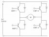
The H bride is similar to the attched circuit.
But instead of using IGBT, I need to use MOSFET.
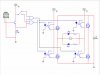
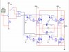
The circuit also need to have optocoupler (each connected to the MOSFET).

The optocoupler will be controlled by a function generator (around 5V).

The motor specs are:
Type: dc permanent magnet motor.
Voltage rating: 180 Volts dc
Power: 500W

The supply specs are:
High voltage, high current (60V, 3A) fixed dc is to power the motor.
An external low power transformer with primary rated for 230V, and two secondary coils of 12V ratings is available to provide the power required for the gate drive circuit.


The difficulties I have is I don't how to choose the MOSFET i need to use, don't know how to choose the optocoupler I need to use.
I read somewhere that I need to use both N-MOSFET (enhanced) and P-MOSFET (enhanced). Why need to use enhanced MOSFET and not depletion MOSFET..? The only thing i know about MOSFET is for N-MOSFET, the source is connected to GND and for P-MOSFET, the drain is connected to GND.

I really need help.. Can somebody please help me.. Thanks..
 

Attachments

  • Motor Drive.jpg
    Motor Drive.jpg
    21.7 KB · Views: 1,844
Look up photo voltaic generators, which are good for the high side mosfets. Any logic level FET and generic opto coupler will do. The photo voltaic generators eliminate the need for P channel fets.
 
Sceadwian said:
Look up photo voltaic generators, which are good for the high side mosfets. Any logic level FET and generic opto coupler will do. The photo voltaic generators eliminate the need for P channel fets.

Sceadwian said:
Look up photo voltaic generators, which are good for the high side mosfets. Any logic level FET and generic opto coupler will do. The photo voltaic generators eliminate the need for P channel fets.
Thanks.. I will look into photo voltaic generators.
But, jst to try to understand, why do some of the H-Bridge circuit use 2 N-MOSFET at the top near the V source and 2 P-MOSFET near the ground..?
Why don't they just use 4 N-MOSFET..?
What is the advantages of using combination of N and P MOSFET..?

When choosing for a MOSFET, several thing I need to consider are:
V(DSmax) - the higher it is, the more voltage is allowed to pass to the motor without burning the MOSFET
I(D) - The amount of current that pass through the MOSFET
Vth (voltage to turn the MOSFET on - the lower the better)
R(DS) during on time (the lower the better)
P(tot) - power disspation - the lower the better.

Is my understanding of the MOSFET correct..? Did I leave anything out..? It is the first time I design a circuit using MOSFET so I am quite nervous..
I am new to reading datasheet and also new to using MOSFET as well...

Thanks for your time..
 
Hmm I smell college work. . .

I'm glad to see you've started asking in the correct manner.

There are many ways of doing this but it depends on what you need to do. Do you need to implement so form of spees control or do you just want forward/reverse?

There are plenty of MOSFETs around that will do this, try looking at a component distributer like Farnell or RS.
 
Sceadwian said:
Look up photo voltaic generators, which are good for the high side mosfets. Any logic level FET and generic opto coupler will do. The photo voltaic generators eliminate the need for P channel fets.
you wouldn't be able to use P-types in this case anyway. The link potential is 60V

Now depending on the quality of the control (and more specifically switching freq) thuse use of photo-voltaic generators to drive teh gate of a FET is out of the question, they do not source/sink that much current and to get switching speeds up you need current (at least 1A if using FET's)
 
Last edited:
Hero999:
Yeah.. its college work..
It need to have forward/reverse control and speed control.. but the speed is entirely control by the function gen. I only need to design the H-Bridge and the optocoupler side..

Styx:
If that is the case, I use 4 N-MOSFET rite..?


I am still curious about MOSFET... I still don't know why people use 2 N-type at the top and 2 P-type at the bottom instead of all N type... I have tried to look on the net and the only thing i can find is for P-MOSFET, the drain is connected to ground but for N-MOSFET, the source is connected to the ground... Another thing is that for P-MOSFET, the V(th) is negative..
In the college, all they taught is N-MOSFET so P-MOSFET is a new thing to me.. Dats why I ask so many questions about it.. Hope to be forgiven..
 
MrNoby. A FET is controled by it's gate to source voltage. The high side N-mosfet of an H-bridge would require a voltage higher than it's supply voltage in order to turn on. You either need to use a boost converter to obtain higher than VCC, or use a floating supply.
 
Sceadwian said:
Look up photo voltaic generators, which are good for the high side mosfets. Any logic level FET and generic opto coupler will do. The photo voltaic generators eliminate the need for P channel fets.
A quick look at solid state relays driven by photovoltaic generators shows turn-on times of several milliseconds, and turn-off times of around 0.5ms. This is a neat concept, and works well if speed is not an issue, but for PWM H-bridges, it seems to me like they would be too slow.
 
You don't necessarily have to PWM both sides of the H-bridge to control speed to a DC motor. You could just PWM the low side. Some motor control methods require both ends though it wouldn't be appropriate for them, there'd be a lot of ohmic losses in the FET during switching.
 
Sceadwian said:
You don't necessarily have to PWM both sides of the H-bridge to control speed to a DC motor. You could just PWM the low side. Some motor control methods require both ends though it wouldn't be appropriate for them, there'd be a lot of ohmic losses in the FET during switching.

True. The PIC18F4520 does this automatically.
 
Here is the driver circuit..
I haven't had much time so I haven't enter the values in yet..
Will do so soon...
Is the general design ok..?
 

Attachments

  • Schematic 01.jpg
    Schematic 01.jpg
    52.1 KB · Views: 1,019
For a start those MOSFETs will blow up, the gate voltage is limited to 15V to 20V depending on the type.

Secondly how are you planning to discharge the gate capacitances to turn the MOSFETs off?

Thirdly I don't think those optocouplers will be fast enough for PWM.
 
Sorry, there is some mistake in the circuit.. The voltage that triggers the MOSFET gate is 12V and not 5V.

Hero999 said:
For a start those MOSFETs will blow up, the gate voltage is limited to 15V to 20V depending on the type.
Will it help if I add 1M Ohm resistor..? Or that resistance will be too high..?

Hero999 said:
Secondly how are you planning to discharge the gate capacitances to turn the MOSFETs off?
Will it help if I connect a 1K Ohm resistor between the Gate terminal and the Source terminal...? This will cause the gate to be discharged to the drain when the circuit is off..

Hero999 said:
Thirdly I don't think those optocouplers will be fast enough for PWM.
Which optocoupler do you recommend..?
 
Below is the updated circuit with the changes.. I added a Free Wheeling Diode for each MOSFET.. Just a note, the VCC for the BJT is 5V, when I tried to change that VCC to 5V, all the other VCC also changes so I cannot change the VCC..
 

Attachments

  • Schematic 02.jpg
    Schematic 02.jpg
    60.6 KB · Views: 837
MrNobody said:
Sorry, there is some mistake in the circuit.. The voltage that triggers the MOSFET gate is 12V and not 5V.


Will it help if I add 1M Ohm resistor..? Or that resistance will be too high..?
Sorry, I misread the circuit, I didn't notice the separate supply for the MOSFET. A 1M:eek:hm: resistor will only make things worse so I don't think it's a very good idea.

Will it help if I connect a 1K Ohm resistor between the Gate terminal and the Source terminal...? This will cause the gate to be discharged to the drain when the circuit is off..
It might help.


Which optocoupler do you recommend..?
I don't know if they are any optocouplers fast enough. You might be able to buy one with a build in MOSFET driver.
 
MrNobody said:
Below is the updated circuit with the changes.. I added a Free Wheeling Diode for each MOSFET.. Just a note, the VCC for the BJT is 5V, when I tried to change that VCC to 5V, all the other VCC also changes so I cannot change the VCC..
Remove the 1M:eek:hm: resistors - they'll stop it working.

I've also noticed that you've used N-channel MOSFETs for the high-side drivers; this will mean that the MOSFETs will not fully turn on.

You either need to use P-channel MOSFETs for the high-side or drive the it with 75V and if you choose the latter you'll also probably need to protect the gate with a zener so it doesn't exceed 20V with respect to the source.
 
Hero999 said:
I've also noticed that you've used N-channel MOSFETs for the high-side drivers; this will mean that the MOSFETs will not fully turn on.
You mean the top two N-MOSFET will not turn on..? Why is that..? I don't quite understand because I am new to MOSFET..

Hero999 said:
You either need to use P-channel MOSFETs for the high-side or drive the it with 75V and if you choose the latter you'll also probably need to protect the gate with a zener so it doesn't exceed 20V with respect to the source.
If I use P-MOSFET, that means that I need to trigger the gate with -Vth rite..?
How do I do that...?

Thanks..
 
MrNobody said:
You mean the top two N-MOSFET will not turn on..? Why is that..? I don't quite understand because I am new to MOSFET..
Because N MOSFETs require the gate to be at a higher potential than the source. With your circuit the gate will be at 15V, therefore the source will flowat at about 5V to 10V giving a massive voltage drop across it and only a small voltage to the motor.

If I use P-MOSFET, that means that I need to trigger the gate with -Vth rite..?
A P MOSFET will turn on when the gete potential is below the source, so if your motor requires 60V and P high side MOSFETs are used they will need 45V to 50V when on and 60V when off.
 
Hero999 said:
Because N MOSFETs require the gate to be at a higher potential than the source. With your circuit the gate will be at 15V, therefore the source will flowat at about 5V to 10V giving a massive voltage drop across it and only a small voltage to the motor.


A P MOSFET will turn on when the gete potential is below the source, so if your motor requires 60V and P high side MOSFETs are used they will need 45V to 50V when on and 60V when off.
Thanks for your explanation.. Initially, i do not really understand.. but after searching on the internet, i found MOSFET application note by DALLAS semiconductor.. Now I understand..
When you say "source flowing at about 5 to 10V", do u mean the V(DS) would be 60V - 10V which is 50V..? Did i understand correctly..? If that is the case then the power loss would be too much...

Can I ask, how to calculate the Voltage at source of MOSFET..? what formula should I use..?

If I use P-MOSFET for high-side driver, the source terminal (of MOSFET) would be connected to the 60V and the drain would be connected to the motor rite..? So, the current would flow in reverse (from source to drain) rite..?

I searched the internet and I found P-MOSFET for the circuit..
The datasheet can be obtained from here..
https://www.farnell.com/datasheets/44775.pdf
From the datasheet, there are 3 things i need clarification..
The first one is V[gs(th)]. The V[gs(th)] needed is -5V. How do I generate a negative voltage..? Is it negative voltage as in the current flowing from source to gate instead of gate to source (as in N-MOSFET)..? So, to solve that, I need to connect the source terminal (of MOSFET) to +ve of 5V supply and the gate terminal (of MOSFET) to -ve of the same 5V supply..?

Second thing is, the minimum V[gs(th)] is -3V, maximum V[gs(th)] is -5V and the V(GSS) is +/- 30V. How do I interpret these data..? Does it means that my gate voltage cannot exceed -5V..? How about the VGSS..?


Yeah.. i posted alot of questiong.... After searching the internet for days, i understand abit of MOSFET but there are still gaps, questions that i still cannot find answer to, things that are still gray and uncertain to me... Thanks for your time and your patience...
 
Last edited:
Status
Not open for further replies.

New Articles From Microcontroller Tips

Back
Top