Continue to Site

Welcome to our site!

Electro Tech is an online community (with over 170,000 members) who enjoy talking about and building electronic circuits, projects and gadgets. To participate you need to register. Registration is free. Click here to register now.

  • Welcome to our site! Electro Tech is an online community (with over 170,000 members) who enjoy talking about and building electronic circuits, projects and gadgets. To participate you need to register. Registration is free. Click here to register now.

h-bridge circuit problem.

Status
Not open for further replies.

ngkyew

New Member
hi,
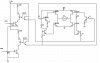
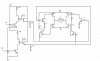
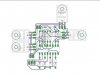
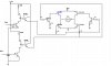
i am facing h-bridge problem with high voltage. i am using 2 PNP and 4 NPN transistor.
PNP: TIP127, and NPN: TIP122

i got problems in calculating the resistor value before the base to control the current flow rate.

that is the value that i should use?

another problem here is, the BJT gets heated up badly when i supply 80V.

the spec of the motor is 80v, 2.778A.

the optocoupler(4n35 is for controlling the speed of the motor and the direction)

need help and advice urgently, thanks for helping
 

Attachments

  • h-bridgeSch..jpg
    h-bridgeSch..jpg
    72.3 KB · Views: 1,578
Last edited:
The 4n35s will not supply enough current to turn on the bottom NPNs, regardless of the base resistance. You need Darlingtons or a pre-driver.
 
i had edited the circuit, thanks.. do you mind checking if this works?
 

Attachments

  • h-bridgeSch1..jpg
    h-bridgeSch1..jpg
    72.3 KB · Views: 591
Still has a fatal flaw. If either (one at a time) 4n35 is turned on, it causes the PNP and the NPN on the SAME SIDE of the HBridge to turn on at the same time. (Instant smoke).

Also, a less serious flaw is that there should be a resistor from each 4N35 emitter to ground to help turn off the base-emitter of the h-bridge transistors.
 
Last edited:
i had edited the 4n35 part and the h-bridge. the resistor value that i put will match ? i am worried the current will flow to ground instead of the base of h-bridge transistor.
 

Attachments

  • h-bridgeSch2..jpg
    h-bridgeSch2..jpg
    75.9 KB · Views: 833
You'll need PNP transistors to drive the bottom transistors.

What purpose do the optocouplers serve?

The 12V's of needs to be connected to the 80V's 0V in order for this to work, so you won't benefit form the isolation provided by it.
 
I agree with Hero; the opto-isolators as you used them do nothing but get in the way.

Here is an LTSpice sim of something that uses non-darlington transistors that will work. It can be driven with two non-overlapping logic signals which share a common ground with the 80V supply. The CW and CCW signals MUST never be asserted at the same time; there must be a few 10s of us deadband between CW and CCW, even if using the opposite direction signal for dynamic braking.

The power dissipation in the H-Bridge power transistors is small. Current spiking is reasonable. All of the transistors must have a Vce voltage rating of >150V. All of the transistors are well saturated when on, with a base current about 1/10 of their respective collector currents. They should be mounted on a heatsink, however.

This circuit does have one major issue, which is power dissipation in R4 and R7; they must be 25W resistors. If you substitute the TIP transistors for my non-darlington transistors, you should be able to reduce the current that flows in R4 and R7 by about factor of 50, reducing the power dissipation. I personally would not try to drive an 80V inductive load with 100V transistors, however...
 

Attachments

  • HB1.png
    HB1.png
    21.7 KB · Views: 460
  • HB2.png
    HB2.png
    32.7 KB · Views: 284
  • HB3.png
    HB3.png
    18.9 KB · Views: 352
  • HB4.png
    HB4.png
    18 KB · Views: 369
Last edited:
H-bridge reverse motor problem

hello. we also have a problem regarding the reverse of the H-bridge motor.
Forward works, backward does not work and we're trying to figure out the problem in the connections. can you please help? if you need the schematic I'll post it here.
 
If backwards doesn't work then you have a problem with the circuits of Q8 or Q2 or Q5.
 
here is our schematic and board for the H-bridge

please help me figure out why the backward motion of the H-bridge motor doesn't work. If there are no problem with regards to the schematic then what would be the possible things why backwards won't work?
 

Attachments

  • schematic..jpg
    schematic..jpg
    56.5 KB · Views: 554
  • board..jpg
    board..jpg
    30.9 KB · Views: 282
Why aren't all the opto-isolator LED Cathodes tied to the same Control input?
 
it's not in the same control input coz we have backward and forward. and the LED is an Ic it's not an individual LED
 
we tried using this connection thru breadboard and it worked. We just don't know why it won't work when we used the connection through the pcb.
 
it's not in the same control input coz we have backward and forward. and the LED is an Ic it's not an individual LED


Then post a truth table of the useful combinations of the voltages on CONTROL 1,2, & 3. I know what an opto-isolator is.
 
Last edited:
The purpose of the opto-coupler is now clear to me. It now seems like isolation is required between the 80V and lower voltage logic circuit.

That circuit is better and is almost right.

The TIL193 doesn't have a high enough voltage rating, you need 80V, preferably 100V and it's only rated to 35V.
https://www.electro-tech-online.com/custompdfs/2010/04/TIL193.pdf

I haven't checked the voltage rating of the transistors, they should all be rated to 100V.

The back EMF diodes are missing, there should be a diode connected in reverse parallel with each transistor to protect against the high voltages generated when the motor is turned off.
 
Status
Not open for further replies.

Latest threads

New Articles From Microcontroller Tips

Back
Top