Electro Tech is an online community (with over 170,000 members) who enjoy talking about and building electronic circuits, projects and gadgets. To participate you need to register. Registration is free. Click here to register now.
Welcome to our site! Electro Tech is an online community (with over 170,000 members) who enjoy talking about and building electronic circuits, projects and gadgets. To participate you need to register. Registration is free. Click here to register now.
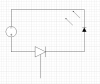
I made a simple thyristor circuit using an MCR 100-6 and an LED in series. When I pump 5V to the circuit, even earthing the gate of the SCR switched the LED on. When I use 3.3V instead, this doesn't happen. Why is this?
Since your circuit is isolated from earth-ground, the long wire just forms one plate of a capacitor. When you touch the wire to ground, the discharge of any static charge developed on the wire triggers the gate. It's a very unpredictable and potential dangers condition for the SCR. In a very dry atmosphere you might get a high enough voltage on the wire to blow the gate-cathode junction. Also you need to insert a current limiting resistor to protect the LED. If you haven't blown the LED you are lucky.
Actually, I first earthed the wire to discharge any static charge. Then I connected the wire again, only one end connected to the gate. The other was not connected to anything. The wire was 3 m long. The SCR switched on. I tried again with a smaller wire. This didn't happen. And yes, why exactly would I need a current limiting resistor? Even if I connect the LED directly to the 5V source, it doesn't blow up.
Is the wire insulated where you are holding it? Are you physically at earth-ground potential. You can be the source to recharge the wire after it was grounded.
Is the LED a pilot lamp assembly, one with an internal resistor? What is your 5V source?
Well heres a question then. Doesn't the current depend on the resistance of the LED? How exactly can we control the current through the circuit? We can control only the voltage.
LED's are a non-linear current devices. They do not have a fixed internal resistance. Once the Vf (forward conduction voltage...~1.7v for a RED led) is reached and it starts conducting, it will pass all the current that the source will supply...until it dissipates so much power that it overheats and blows up. That's why there should always be a current limiting component in series with the LED. I have seen some circuits (Christmas ornaments) where the battery voltage and the LED's Vf are so close that internal resistance of the battery acts as the current limiting component.
A source will put out as much current as it can, and an LED will use as much current as it is supplied. A series current limiting device (resistor) will drop the difference between the battery voltage and the LED's Vf. Vbattery = Vresistor+Vled and the circuit current (Iresistor or Iled) will be Iled = Vresistor/Rresistor.
How you can connect a bare LED across the 5V lines of a PC power supply and not have it die is beyond me.
This site uses cookies to help personalise content, tailor your experience and to keep you logged in if you register.
By continuing to use this site, you are consenting to our use of cookies.