Continue to Site

Welcome to our site!

Electro Tech is an online community (with over 170,000 members) who enjoy talking about and building electronic circuits, projects and gadgets. To participate you need to register. Registration is free. Click here to register now.

  • Welcome to our site! Electro Tech is an online community (with over 170,000 members) who enjoy talking about and building electronic circuits, projects and gadgets. To participate you need to register. Registration is free. Click here to register now.

Grid Tie Inverter Schematic 2.0

Status
Not open for further replies.
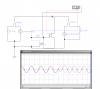
I make the 3 fase AC short switch with 2 triacs, 2 optoisolators and some resistors to short the PMG output above 60V.
It seams to work fine.
Than I make anoter short switch with heavy 2 automobil 5 legs relais 40 A to safe the wind maschine wen a blackout ocur, and anoter 2 same relays to conect a dum load at 55 V.
I noticed that wen the relays switch, then i can hear sparks in the China inverter... and it smells as burned.
How I vcan make good filters for these relays? to avoid these sparks?
 
Well I am suspecting you killed the Chinese inverter unit due to your triacs and relays creating high voltage inductive spikes in your generators output as they switched on and off at different points in the AC cycles as they are trying to keep the generator loaded down. :(
 
I am trying to make a load controler. I also read about heavy relay to short the PMG...
Did you have sugestions to make these controls?
 
SCR's work fine if you need a way to have the load or braking system lock on and not drop out until the unit has completely stopped moving or until a manual disconnect switch drops the power going through the SCR so it can reset its off state.

As far as controls go you need to define what exactly you want to control and where first. :confused:

Variable load, complete shut down, or a combination of both and will they be done from the AC side or the DC side of the system?
 
Now I want conect a automatic dum load wen the PMG voltage arrives 42VDC, and desconect under 38 VDC.
I am learning about e-switches, and make some tests to learn more...
I burned some igbts with constant load (VDC), because the gate voltage was to smal, about 5 V... (obteined from resistors betwen the PMG poles). So after much seek I find that the IGBT gate on voltage must be rapid 15 V signal. And the off voltage must be -5 to -15 V. The +15 volt I can make with a diac and resistors, but I dont know how to make a simple automatic -5 to -15V gate off voltage. Any sugestions?
 
Just use common IGBT/Mosfet driver IC's like the ones I listed in the schematics here to do the gate drive work.

International rectifier makes a bunch of dedicated driver IC's for many different voltage and gate drive applications so if you need something more specific they probably have it.
 
Very interesting subject. I'm thinking about building a grid tie inverter, but I'm not sure, is building it from scratch the way I should go. I have an used double conversion UPS (APC SURT3000XLI) which I'm trying to implement into my solution. At the moment the UPS is used as UPS, behind of it is all networking and home automation products. The UPS is using internal and external batteries at 192V. I have in mind of building solar cell panels, 36V a panel (6*12 cells in panel) and 6 panels in serial connection, with total output voltage 216 V and connect this to the online UPS external batteries connector. I'm thinking about possibilities to modify the SURT3000XLI UPS inverter and make it work as grid tie inverter. Need to figure out, is there chance for modification and add inverter synchronization and grid down protection to this UPS. The UPS doesn't have output transformer. I also don't have the UPS circuit diagram and I'm not sure, is there any chance to get it at all... But has someone ever try'd to build grid tie inverter from UPS? Our voltage is 220V @ 50 Hz.
 
Last edited:
At lower input voltages and power levels Push Pull driver circuits work very well and are the simplest to make but as the input voltage goes up the cost of switching devices that can handle the higher peak voltages and currents gets cost prohibitive for the design at some point.

My whole goal for these threads was to show how to do basic GTI builds on the cheap with common nonspecific parts and still be reasonably efficient and reliable to use.
 
Here in Brazil the eletronick electrick registrators used in the new stupid grids are unidirectional.
So, if you produce more energy than you use, you have to pay for the injected energy as it is consumed from you...

Tests with inverter has shown, that in my region used "stupid registraters" too :facepalm:.

I have think to make direction indicator. But there is a gap in my knowledge.

To do this there are two transformer (on entering the house) is enough for current and voltage to determine the phase shift between 180?
Detector output - digital signal which will reset the drivers (must succeed the PWM).
What could be the problem here?

upd. there is nothing new under the sun. The idea is called grid tied limiter.

**broken link removed**
 

Attachments

  • dir ind.png
    dir ind.png
    28.1 KB · Views: 655
Last edited:
Seriously? If you have to ask that on this thread I have to assume that reading and attention to detail is not really your strong point. :rolleyes:

Do you stop at a gas stations, park next to the fuel pump and then go in and ask them if they sell gas too? :facepalm:
 
Seriously? If you have to ask that on this thread I have to assume that reading and attention to detail is not really your strong point. :rolleyes:

Do you stop at a gas stations, park next to the fuel pump and then go in and ask them if they sell gas too? :facepalm:
 
Last edited:
No. Updates. The given schematics and information still obeys the laws of physics today as they did then. :p

Setting one of these circuit up for solar power is not any different than for any there power source. You just have to set up the control system to connect and disconnect from the grid for what parameters your system operates at.
Everything else is just a matter of using properly sized components to handle the power levels you have available. ;)
 
Hello sir, thank you very much for the information you provide.
I have read everything carefully, I have many doubts but I will start with one: how does the inverter solve the neutral take on grid integration? I think the two ends of the output transformer are "alive". Thank you.
Using google translator.
 
I find this site a great source of ideas and to do lists which I add to my bucket list. Special thanks tcmtech for his incredible inputs.

Now reading all this makes me wonder if there is a simpler way to achieve the benefits of both worlds. Please excuse any dumbness as I'm a novice.

Since we have power conditioning experts on board my question is if I could simply use DC/AC transformers to supply unregulated and unsynced AC output from each panel, and somehow get a pure AC sinewave output from it like combine 12 or more AC outputs.

Will this make grid tie more efficient by having one circuit at the end to combine, regulate all phase if they all are the same type of transformer with same winding?

My other problem I'm dealing with is if I can use my ups as a switchover during power cuts to supply pure sine wave signal to activate my grid tie inverters. I tried to connect directly but it causes overvoltage as the power is pushed back to my ups from grid tie inverters, I did a lot of reading and am not sure if I have a solution. I am thinking of using IGBT to regulate the flow from ups to grid tie at the load junction. Since the IGBT allows power to flow from only emitter to collector will that prevent reverse flow to the UPS ? I mean we have a lot of power cuts and my Gridtie cuts off over hundreds of time per day and this will be also a means to provide a regulated power source to sync my grid tie inverters.

TIA for any advice ! :)
 
The most practical thing for stand a lone power from your solar panels would be to feed them to a properly sized battery bank and use a properly stand alone power inverter.

Grid tie inverter ters were never meant to be connected to other solid state power sources since a stand alone power inverter cant take power back form them like a utility line or even mechanical spinning mass generator can.

As far as s IGBT they are just a high capacity transistor with a mosfet driving their base and will conduct in reverse just as most any other bipolar switching device will.
 
Thanks for your input tcmtech. I know that we are going against known and popular beliefs, but I'm also working with companies that have overcome these problems at a great price like Magnum outback systems or SMA but are too expensive for third world countries.

So can we make a fresh start, to simplify, this was my thought process. Every grid tie Inverter connected to my solar panels right now converts DC to AC and syncs the phase output with the grid, while providing monitoring of input and output voltages and power line communication the standard grid tie option.

Now suppose we simply convert solar panel 24v output DC to AC with a power monitor at the solar panel junxrion and then combine all panel outputs together using a grid tie device that can regulate and generate a pure sine wave output of the unsynced AC ouputs from all panels, we have reduced the overall cost by more than half, cost being the major factor that can drive this technology to the masses. I hope to solve this first, I also read that unlike mosfet an IGBT allows power to flow I one direction from collector to emitter and so I hope my second problem may be solved with this, but I keep my fingers double crossed :)
 
Status
Not open for further replies.

Latest threads

New Articles From Microcontroller Tips

Back
Top