Hi MrAl,
I believe our first transfer function is correct, but the second one isn't. I went over the math myself and will show you my results.
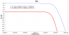
Conventional Low-Pass Filter
Final Equation
[LATEX]Amplitude = \frac{V_{IN}}{\sqrt{1 + Z_R^2 \omega^2 C^2[/LATEX]
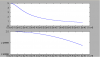
Low-Pass Filter With Load
[LATEX]i_1 = i_2 + i_3[/LATEX]
[LATEX]i_1 = \frac{V_{IN} - V_O}{R}[/LATEX]
[LATEX]i_2 = V_O j \omega C[/LATEX]
[LATEX]i_3 = \frac{V_O}{R_L}[/LATEX]
[LATEX]\frac{V_{IN} - V_O}{R} = V_O j \omega C + \frac{V_O}{R_L}[/LATEX]
[LATEX]V_{IN} = V_O + V_O R j \omega C + \frac{V_O R}{R_L}[/LATEX]
[LATEX]V_{IN} R_L = V_O + V_O R j \omega C + V_O R[/LATEX]
[LATEX]V_{IN} = V_O(1 + R j \omega C + R)[/LATEX]
[LATEX]V_O = \frac{V_{IN} R_L}{1 + R j \omega C + R}[/LATEX]
[LATEX]\frac{(R_N^2 + I_N^2)}{(R_D^2 + I_D^2)}[/LATEX]
[LATEX]\frac{(V_{IN} R_L)^2}{(1 + R)^2 + (R \omega C)^2}[/LATEX]
[LATEX]Amplitude = \sqrt{\frac{V_{IN}^2 R_L^2}{1 + 2R + R^2 + R^2 \omega ^2 C^2}}[/LATEX]
Final Equation
[LATEX]Amplitude = \frac{V_{IN} R_L}{\sqrt{1 + 2R + R^2 + R^2 \omega^2 C^2}}[/LATEX]
I believe that's correct?

")