EN0
Member
Hey Everyone,
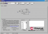
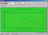
I ordered a HP-50G calculator recently, which should arrive sometime soon, for school this year. I would like to graph several transfer curves of various filters. For instance, I would like to graph the transfer function of the following of a typical RC low-pass filter (see attachment):
The equations below apply:
[LATEX]V_O = V_I_N \frac{X_C}{Z}[/LATEX]
Where:
• [LATEX]X_C = \frac{1}{j \omega C}[/LATEX]
• [LATEX]Z = \sqrt{R^2 + X_C^2}[/LATEX]
Therefore:
[LATEX]V_O = \frac{\frac{1}{j \omega C}}{\sqrt{R^2 + (\frac{1}{j \omega C})^2[/LATEX]
Graphing with a complex number kind of throws me off, would someone show me how to graph the equation with the values above?
I'd appreciate any help!
Thanks,
Austin
I ordered a HP-50G calculator recently, which should arrive sometime soon, for school this year. I would like to graph several transfer curves of various filters. For instance, I would like to graph the transfer function of the following of a typical RC low-pass filter (see attachment):
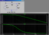
- C = 10µF
- R = 10kΩ
- Vin = 5V
The equations below apply:
[LATEX]V_O = V_I_N \frac{X_C}{Z}[/LATEX]
Where:
• [LATEX]X_C = \frac{1}{j \omega C}[/LATEX]
• [LATEX]Z = \sqrt{R^2 + X_C^2}[/LATEX]
Therefore:
[LATEX]V_O = \frac{\frac{1}{j \omega C}}{\sqrt{R^2 + (\frac{1}{j \omega C})^2[/LATEX]
Graphing with a complex number kind of throws me off, would someone show me how to graph the equation with the values above?
I'd appreciate any help!
Thanks,
Austin
Attachments
Last edited:
")