Continue to Site

Welcome to our site!

Electro Tech is an online community (with over 170,000 members) who enjoy talking about and building electronic circuits, projects and gadgets. To participate you need to register. Registration is free. Click here to register now.

  • Welcome to our site! Electro Tech is an online community (with over 170,000 members) who enjoy talking about and building electronic circuits, projects and gadgets. To participate you need to register. Registration is free. Click here to register now.

GPO 36 master clock contact impulse debouncer

Status
Not open for further replies.

RODALCO

Well-Known Member
GPO 36 master clock contact de-bouncer

I decided to build this circuit after my Gents GPO 36 master clock started having the odd extra pulse bounce and occasional pulse miss as well, which caused the slave dials to get out of step.
As I was aware that the 30 seconds output contact is not supposed to driving the slave clocks directly, although the setup was like this in my GPO 36 master clock for the pilot dial fitted in the door.
Attached schematic will show the components and I set up the capacitor time constant to about 1 second.
It doesn’t matter if the clock pulse is shorter than ½ second or bounces twice when the pendulum pushes the ratchet through the 30 seconds lower cog of the count wheel.
It will give a 1 second impulse.
The circuit is very compact in use and can easily be fitted in the clock housing.

The circled numbers in the attached circuit refer to the top connectors of the GPO master clock.
To note is that I changed the polarity of the clock supply to be able to use a NPN darlington transistor.

Clock contact row
1—2—3—4—5—6—7—8—9—10

1—1sec
2—6sec
3—30 sec impulse to D1
4—n.a.
5—Positive 12 Volts dc
6—Negative
7—pendulum drive
8—to slave dials
9—spare
10—spare

Another beauty of this simple circuit is that it is perfect to be used for synchronising another pendulum clock(s).
The “slave” pendulum clock requires a piece of soft steel/iron to be attached below the bob to be attracted by the electromagnet.
It will require it’s own circuit but the materials cost virtually nothing anyway.
I have a ¾ seconds Bürk pendulum master clock being “locked in”, with the 30 seconds impulse from the Gents 1/1 seconds master.
I set the time constant to about ½ second and drive a 47 ohm coil which attracts the pendulum at the end of the swing.

I got both clocks running in perfect synch via a 30 metre long cable as the “slave” pendulum clock is in the workshop in my garage.

Photo’s

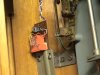
5052 is the circuit in the GPO
5053 are the top terminals of the GPO
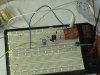
5055 is the second circuit driving the “slave” pendulum
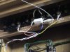
5058 is the iron slug under the slave pendulum.

RF.
 

Attachments

  • GPO master clock contact debouncer.GIF
    GPO master clock contact debouncer.GIF
    21.7 KB · Views: 1,869
  • DSC05052.JPG
    DSC05052.JPG
    426 KB · Views: 1,337
  • DSC05053.JPG
    DSC05053.JPG
    417.8 KB · Views: 995
  • DSC05055.JPG
    DSC05055.JPG
    451.9 KB · Views: 955
  • DSC05058.JPG
    DSC05058.JPG
    384.6 KB · Views: 996
Hi Ray

Great project!!!

I have several GPO's set up so the circuit will be great for syncing!!.

The only time I get any extra pulses to the slaves is either when the 30 sec contact pawl jams or acts up, another is when I assume It's not running with enough power to run both the pendulum and any slaves.The error in this situation happens only at the exact point when the hip/toggle impulses the pendulum and when the 30 sec toothed wheel allows the slave contact to be pushed !! hope you understand? each impulse requires power so something as to give, sometimes it's the slave and thus the time or sometimes it's the pendulum impulse (it takes more pushes with the toggle than normal)

As you rightly say with GPO's we should really run then slaves on relays with a separate power source.

Anyway when I get a moment I will make up the circuit.

Your slave pendulum !! is this another gpo. ? and if so I would then assume you remove the hipp/toggle. I have four gpo's in a row and would run two masters and two slaves. and maybe a free pendulum on it's own. What do you think??

Ok mr. youtube I would like to see the new syc circuit in action, any chance of doing a vid for us to see?

Regards
 
Last edited:
I was confronted with a problem with a Synchonome master clock, a couple of years ago. Like this one: **broken link removed**

Similar concept to the GPO master clocks, I'm guessing?

Problem with this one was not missing pulses -it just wouldn't run at all for more than a couple of hours! Over the years, everal people reckoned they could fix it -and had failed.
In the end it hadn't run for over ten years, which seemed a shame.

I didn't want to remove or modify anything in the clock itself -- it's still a lovely piece of machinery, even if it doesn't run - so I simply cobbled together a 30 second timer, with a small power supply (battery supported, of couse!:)) and used a 250mS pulse to an open drain output from a power mosfet to drive the secondaries in series (of course!). To adjust the time - simply turn to a 2 second 'advance' timer mode, or if it's fast, just stop it for the required time!

Been running for nearly two years now - gains about half a second a day (depending on the weather, and the club house gets pretty cold in the winter -no crystal oven here, I'm afraid!)

Short video of the installation here if you're interested:

Boscombe clock on Vimeo

No -that's not me on the ladder!!:)

Great fun project -I enjoyed it a lot. And everyone's happy. The clock works, and the original has not been touched.

One day, so they say, they're going to get someone to completely overhaul the original.---

Better start saving now. That kind of expertise doesn't come cheap!!

They are lovely these old 'master' clocks though! :)
 
Hi Mark, YouTube link will follow soon.

My current temporary set up is a bit rough.

The 30 seconds toothed countwheel contact is ideally not supposed to directly switch the slave dials although it is done in many cases. ( I read it somewhere on the web by a GPO expert).
It can sometimes give a double bounce proabaly in the case as you mentioned when the 30 seconds contact is closed and the slave contact.

This simple circuit has a fixed timeconstant determined by the capacitor C1 and bleedresistor R2.

I run my GPO directly of 12 Volts dc with a 15 ohm 5 watt resistor in series with the Hipp Toggle. the Hipp coil is 10 ohms so the impulse current is 0.48 Amps.

The slaves are run from a separate 12 volts supply in my current test set up as my workshop is ±20 meters away from my GPO.
Although you can run them from the same 12 volts supply as long it has the capacity.


The slave pendulum is not an other GPO but a Bürk 3/4 seconds clock with graham escapement and weight drive.

I think that by correct set up of the iron slug under the pendulum and position of the drive coil you should be able to synch two GPO's with no problem.
Leave the Hipp Toggle intact, which provides the main drive to the slave master clock.
If penduli of the slave are drifting a little the coil will try to increase/decrease the speed of the pendulum of the second clock and keep it locked in.

Regards

Raymond
 
I was confronted with a problem with a Synchonome master clock, a couple of years ago. Like this one: **broken link removed**

Similar concept to the GPO master clocks, I'm guessing?

Problem with this one was not missing pulses -it just wouldn't run at all for more than a couple of hours! Over the years, everal people reckoned they could fix it -and had failed.
In the end it hadn't run for over ten years, which seemed a shame.

I didn't want to remove or modify anything in the clock itself -- it's still a lovely piece of machinery, even if it doesn't run - so I simply cobbled together a 30 second timer, with a small power supply (battery supported, of couse!:)) and used a 250mS pulse to an open drain output from a power mosfet to drive the secondaries in series (of course!). To adjust the time - simply turn to a 2 second 'advance' timer mode, or if it's fast, just stop it for the required time!

Been running for nearly two years now - gains about half a second a day (depending on the weather, and the club house gets pretty cold in the winter -no crystal oven here, I'm afraid!)

Short video of the installation here if you're interested:

Boscombe clock on Vimeo

No -that's not me on the ladder!!:)

Great fun project -I enjoyed it a lot. And everyone's happy. The clock works, and the original has not been touched.

One day, so they say, they're going to get someone to completely overhaul the original.---

Better start saving now. That kind of expertise doesn't come cheap!!

They are lovely these old 'master' clocks though! :)

Hi rogs

Nice sync master!!! wish it were mine.

So you don't have the master running anything? From my experience with Synchronome it's all down to fine tuning.I've never really had much difficulty in getting then to run so long as everything is intact.

If you were closer to me I would have liked to come down and see what I could do with it. From what I can see it's should be pretty straight forwards.

I see in the Vid. the pendulum actuator isn't resetting!!! but that's probably just because you dont't have any power hooked up to it.

I like Rodalco have a unhealthy interest in Master clocks of all sorts.Turret clocks is also another interest of mine.

I'm sure we can get that clock running so if there's anything I can help with please let me know.

Cheers.
 
Hi Mark -

Thanks for the offer!

In fact, it is actually extremely unlikely that the clock will be returned to it's full glory, in it's present location, for a number of reasons.

The clock was initially installed in the Boscombe Cliff bowling club pavilion, as far as I can tell, in 1927, and ran successfully for many years, with regular servicing.

For the last 25 plus years it has had a rather chequered history.
Initially, as I understand the story, quotations for restoration were sought from professional horologists, but were not taken up due to lack of funds. Various people (of differing abilities) tried all sorts of repairs and adjustments, but none succeeded in restoring the clock to a working state. At some stage a replacement power supply was fitted (that's the large grey box next to my new one in the video).

Not everyone was keen to have the clock running anyway! It is located in an area of the pavilion where the honours board is situated -a fairly acoustically 'live' area - part of which is now leased out as a cafeteria, open to the public. I'm afraid that many folk where not keen on the loud reset 'clonk' every thirty seconds, and were not sorry that the clock didn't work!

I was asked some two years ago by the club vice captain to see if there was any alternative way of at least making the outdoor 'slave' on the clubhouse roof function.

Once I'd seen the clock itself I decided it would be unwise (and unforgivable)to play about with such a beautiful object without knowing what I was doing, so I simply removed the series output wiring, and made and fitted a solid state version of the clock 'pulse' generator, so that the outside clock ran once again. Comments were received from many visiting members from other clubs -some claiming it was the first time they had seen the clock running regularly for over 20 years!

Unfortunately, it looks as if the area around the actual location of the clock may have to be modified soon, to meet disabled access equirements, so the the clock itself may have to be moved --and if that happens, I suspect it may now well be sold, as surplus to requirements, especially as the outdoor 'slave' no longer requires it's master to function!

That might be a good idea in the long run -- at least it might then be restored to it's former glory!

I can understand why you find these clocks so fascinating, they really are objects of great beauty IMHO -even if they do make loud 'clonks' every thirty seconds! :)
 
**broken link removed**

Above link mentiones the 30 seconds contacts and it's loading.

Nice clock on the link.
 
YouTube - GPO 36 master clock impulse debouncer

YouTube video of current temporary set up under test, made for Mark

Regards Raymond

Great Guns Ray!!

Cheers for that.It's very good to see it running.

Just so I know I follow-

You say the slave electromagnet requires it's own circuit!! do you mean another other than the one in this thread ?
Does your Burk pendulum receive a 30 sec sync pulse?

When used in a sync circuit is it connected the same as when used as a slave debouncer?

Questions questions questions!!!!

Cheers
 
Last edited:
synchronising

Hi Mark,

The reason I run an additional impulse circuit is that it can be set up for it's own time constant to drive an additional pendulum clock.

As different clocks have their pendulum time constants like 1/2 , 2/3, 3/4, 5/6 and 1/1 seconds. A different amount of energy is required to keep them in synch.

The Bürk has a 3/4 seconds pendulum which is basically a 80 beat movement.
It gets the "correction" impulse every 30 seconds.
I found by trial and error by putting in different cap values (47, 100, 220 uF) and bleed resistors (100, 470 1000R) that a 1/2 second shot at the synchronising coil keeps it in perfect synch.
If the impulse is too long it may interefere with the pendulum too much when it does the second swing after the synching process.

Even if I have to adjust the Gents master by adding a small weight on the pendulum to increase its speed. The slave pendulums will get synched up in speed and remain locked in during the process.

More questions please ask

Kind regards, Raymond
 
To add

The one for the Gents is at the left hand side (green led, orange 12 volt 20 Amp relay) within the Gents GPO, I give the Gentss slaves an 1 second impulse via that circuit.

The synchroniser is on the white breadboard on my messy workbench in the garage from where it controls the Bürk every 30 seconds.

Hi

Yep knew that from the vid, just wondering about where in the Gent master is the long wire going to the workshop connected,
IE. is the (slave/remote pendulum sync circuit) connected to the master the same as the slave debouncer circuit IE. 3,5 and 6?

Cheers
 
Last edited:
That wire is connected to the 30 sec impulse contact from the Gents.

It is basically in parrallel with the impulse debouncer. the 30 second contacts basically charge up via a diode two 100 uF caps and drive the basis from the BD647. (darlington transistor). a normal BD139 should suffice as well with no problems

So from terminal 3 there is one wire going to the impulse debouncer circuit in the Gents GPO and one wire going via the black aligator clip into the 6 core to the breadboard synchroniser and then to the clock under test in my workshop.

Terminals 3,5 and 6 are correct.
 
Status
Not open for further replies.

Latest threads

New Articles From Microcontroller Tips

Back
Top