Continue to Site

Welcome to our site!

Electro Tech is an online community (with over 170,000 members) who enjoy talking about and building electronic circuits, projects and gadgets. To participate you need to register. Registration is free. Click here to register now.

  • Welcome to our site! Electro Tech is an online community (with over 170,000 members) who enjoy talking about and building electronic circuits, projects and gadgets. To participate you need to register. Registration is free. Click here to register now.

Going insane with thermostat design

Status
Not open for further replies.

namezero111111

New Member
Hello eletronic folks,

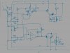
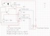
I am a hobbyist trying to build a thermostat that both heats and cools. I have come as far as having the circuit built, but what happens is that once the relay coil switches on, it causes a voltage drop in the whole circuit, so when the temperature change is very gradual the relay switched on and off multiple times before staying on. I have tried putting capacitors between the transistor and relay so soften that effect, but it still occurs.

The problem, I believe, is that the transistor doesn't switch enough power when the IC turns high. I tried adding another transistor in series with the first one (NPN switching PNP transistor) but that just created smoke :(

I'm confused as to how to give this setup a better "snap"...

I have attached a picture of the circuit diagram and hope you can help me. Thank you so much!

-Andy
 
Last edited:
It's difficult to see which wire are connected by looking at your schematic. Please repost with a black dot where the wires join.

The problem you're having is probably because there's no hysteresis and can be solved by adding a 1M resistor from the output of each comparator to the + input.

What ICs are you using as comparators?

Do they have push-pull outputs or are they open collector? If they're open collector, you'll need a pull-up resistor.

The top transistor is upside down or should be PNP.

Neither transistor has a current limiting base resistor, although this won't be a problem if the comparator outputs are current limited.
 
Thank you for your quick answer. I have reconnected the lines with dots.

I am using an LM339 comparator for this.
There is a variable resistor on both outputs that was intended to control hysteris, and I believe it does, but I'm not too sure.

I don't know about push-pull outputs or open collector, I'm not an electrical engineer, but I think the resistors I was talking about above may be for the "pull-up".

EDIT: I have a more "current" diagram that I drew by hand, but it is less legible, should I scan and post it?
 
Last edited:
I was wrong about the top transistor being drawn upside down.

Your schematic makes much more sense with the dots.

The top comparator is connected as a linear amplifier and will oscillate at some high frequency. The feedback resistor should go to the + input not the - input.

Both transistors are connected as emitter followers which isn't the done thing as it results in a loss of about 0.7V, although isn't an issue here.

An LM339 has open collector outputs which, in this case, are pulled up by the 3k9 resistors.

The diodes that connect to the 22k resistor will cause latch-up when the output goes high. I'd recommend replacing them with 100k resistors and you might as well use a fixed resistor for the feedback. The top resistor should also go to the + input not the - input.
 
Last edited:
Hmm I will try this on a breadboard since I think I have to start all over now :(
I had also installed capacitors between the transistor and relays to help overcome the problem, and connected the other side of them to ground so the capacitor would "charge up" before switching the relay so it wouldn't cause a drop in the system.

I have attached the most currect copy of the (handdrawn) circuit so you can see what I modified from this version just to be sure your adjustments would still work.


I guess then two or three transistors in a row wouldn't do much good hm?

EDIT: The rheostat between the + input for the second IC is used so that there is an "off" position between heating and cooling so that it doesn't go directly from one to the other, and depending on how this is adjusted it is a larger or smaller temperature range.
 

Attachments

  • 5 001.jpg
    5 001.jpg
    102.9 KB · Views: 645
Last edited:
What are you heating / cooling with this?

It is for my fish tank and it powers relays that reverse a peltier's voltage for either heating or cooling. Heating and cooling also both switch on a far and pump that pumps water through a heatsink on the peltier to keep the temperature in the fish tank at 75* +/- 1*.

It all worked except the relays rapidly switching right around the on/off point for cooling since the temperature change was so gradual.

I wonder if the voltage regulator has something to do with this, because before switching on the voltage is 12v, but after the peltier is on it drops below 12v to 11.8, so maybe the circuit also gets confused by this.

Again sorry if I sound incompetent, I'm a pilot, not an engineer : )
 
Looking at that schematic makes my head hurt. :D

I still don't know what you're trying to achieve by having diodes connected to the inputs of the comparators, they'll only cause trouble (especially the bottom one, which will cause latch-up as I told you before) so take them out as I said before.

Where is the temperature sensor?
 
It sounds like you may not have enough current in your power supply, try running the peltier from a separate source.
 
Looking at that schematic makes my head hurt. :D

I still don't know what you're trying to achieve by having diodes connected to the inputs of the comparators, they'll only cause trouble (especially the bottom one, which will cause latch-up as I told you before) so take them out as I said before.

Where is the temperature sensor?

Haha I'm sorry about that and I really appreciate your help and everybody elses : )

The temp sensor is the 50k thing on the lower left where the two diodes are. I will take those out. My only reasoning of having them in there was so the two comparators would not interfere with one another through the feedback voltage.

It seems that a hot/cold thermostat is an extremely complicated thing to build : (
Overall, do you think such a circuit would function reliably though?

Mike2545 said:
It sounds like you may not have enough current in your power supply, try running the peltier from a separate source.
The power supply should be fine, it's a computer supply I modified according to an online document and it puts out 12v 18A, the peltier should use 15A it says on the website. And I looked up the ATX specs, it seems like 11.8 is still within the specification limitations of output voltage for the 12v rail.
 
Last edited:
Which relay is this circuit supposed to switch at what temperature?

Also, does the relay simply reverse the power to the Peltier cooler so it heats rather than cools vice versa?

Wouldn't it be better if it turns the Peltier off at certain temperatures to save power?

The hot/cold feedback shouldn't interfere as long as it's designed correctly.

Yes, that's why it was important to have the off period designed in that is controlled by the rheostat on the upper IC.
Basically, how it works is the thermostat says "cool now" and the cold relay in the schematic then switches a higher current automotive relay that provides power to the peltier.
It the thermostat says "heat now" then the same relay is switched, plus two more relays that switch the polarity of the peltier.
That part, in fact, is the only thing about my project that works so far :( I've been stuck on this thermostat for over a month now trying different things and are about to scrap the project or make it cooling only because nothing seems to work with my thermostat : (.
Even the resistor and capacitor values etc in the thermostat are trial and error since I wouldn't know how to calculate them properly.

I tried finding circuits online, but nothing that has both heating and cooling with an off period in the middle.
 
Yes! Exactly! That's an excellent description of what I'm trying to accomplish!

Here's the part that controls the peltier according to what the controller says needs to be done:
 

Attachments

  • heatcool.JPG
    heatcool.JPG
    147.6 KB · Views: 274
In have a question: I rebuilt everything from scratch according to the second diagram minus the two diodes that can cause "latch up". That means I have 330k resistors providing feedback to the + input, but I still have the relays "humming" as gradual temperature changes occur, even with only an LED providing load on the relays. How can that be???
 
Where's your reference voltage?? It looks like you are taking it from a resistor voltage divider off your main power rails. Is that 12v regulated? If not, it needs to be. And you need some caps on the + and - inputs of your comparators. :)
 
It depends on the temperature sensor, if it's a thermistor it doesn't matter since the potential divider ratios will remain constant regardless or the power supply voltage.
 
Wow I really liked the second article you posted! It gave me a much better insight on how the comparator works and what it does, although I'm confused by some of the terms they used.

I guess I never thought about using the low output with a PNP transistor; I always used the high output with an NPN transistor. Hmmm...

Do you think the 330k hysteris in the circuit I uploaded is too little?

And also, due to the voltage drop below the 12v to 11.8v, do you think it is recommendable to run the circuit at 5V instead? I was thinking about doing that, only I'd have to get 5v relays. Wouldn't that decrease the accuracy though due to the voltage drop per * fahrenheit being lower than at 12v?

EDIT: Yes, I am using a thermistor for sensing termperature. I encased it in this liquid electrical tape that dries into rubber to make if waterproof.
 
Last edited:
Status
Not open for further replies.

Latest threads

New Articles From Microcontroller Tips

Back
Top