Continue to Site

Welcome to our site!

Electro Tech is an online community (with over 170,000 members) who enjoy talking about and building electronic circuits, projects and gadgets. To participate you need to register. Registration is free. Click here to register now.

  • Welcome to our site! Electro Tech is an online community (with over 170,000 members) who enjoy talking about and building electronic circuits, projects and gadgets. To participate you need to register. Registration is free. Click here to register now.

Gigantic Transformers Galore!

Status
Not open for further replies.

solis365

New Member
My university likes to throw out old equipment, so naturally, when they do, I have a field day.

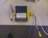
Today they threw out a gigantic uninterruptable power supply (APC). It had a 250V plug and several 240 and 120 sockets on the output. It was probably used for backup in our Semiconductor Manufacturing Laboratory (I go to Rochester Institute of Tech) .

Anyway, someone had gutted it before I got there and I found some absolutely massive transformers (about 8" cubes). There were also some smaller ones. I have always found that transformers are difficult to find datasheets for.

does anyone know what the basic markings on transformers mean?

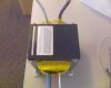
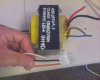
The one I have on my desk right now says:

430-2054A.3 (could be -3)
CLASS 130(B)Z150H
E154515 LEI-4 OH10


One side has 3 wires, orange, black, white
the other side has 5 wires:
3 are heavier gauge than all the others and are red, white, black
2 are the same guage as the wires on the other side and are orange and brown.


I assume the heavier gauge are the primary but im not sure why the secondary would be split over the two sides. It may be a 220V transformer, instead of 110... not sure how to tell.

I have 2 other transformers in my car. I can get the numbers from them but if theres something simple about transformer numbering that im missing i can find them myself once i learn what it is.

Thanks


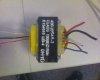
absolutely massive transformer numbers:

430-7128
CLASS 180(H) R333H
LEI-4 E154515 2D08

giant white and black wires on one side
blue, black, red, white wires on other side into plastic connector.
 
Last edited:
On the first one - did you happen to see any capacitors connected directly to the transformer?

**broken link removed**

I've seen some old-style UPS (and some monster industrial ones) for sale that were described as "ferroresonant", but the boat-anchor aspect/forklift requirement always convinced me to not to take a closer look.

There's also a paragraph on wikipedia:
Voltage regulator - Wikipedia, the free encyclopedia
 
On the first one - did you happen to see any capacitors connected directly to the transformer?

**broken link removed**

I've seen some old-style UPS (and some monster industrial ones) for sale that were described as "ferroresonant", but the boat-anchor aspect/forklift requirement always convinced me to not to take a closer look.

We've got some at work, we rescued them years ago - we used to run two relay systems (antique cable TV). They were put in before my time, using all valve repeaters, and initially required permanent adjustments of repeater output levels. It was eventually decided that the problem was due to mains variations, and constant voltage transformers were fitted on the repeaters, which cured the problem.

When we scrapped the syatem back in the 70's (with big smiles on our faces) we salvaged the transformers.
 
I looked up the UL file number (E154515) on the ul site.
OBJY2.E154515 - Systems, Electrical Insulation - Component

It didnt give much detail but it does indicate they are isolation transformers.

I also found this: Three-phase electric power - Wikipedia, the free encyclopedia the wire colors seem to match.

I do not think they are isolation transformers, as isolation transformers would only have 4 leads, or a symmetric distribution of leads (even numbers of leads). I wouldn't say that that sheet you found indicates they are ISOLATION transformers, only that they are INSULATED transformers ;)

I am in the US and neither of those wiring colors seem to match, unfortunately. (Actually, I'm glad they arent three-phase as I wouldnt have much use for it...)


@hijames: The supply had already been gutted before I got there, the 3 transformers were just mounted in the box and there was nothing left but a broken fan inside (the battery compartment was like 2 feet long by 6" by 1 foot high... would have liked those!)

I really suspect they are mains transformers, but I do not know how to make sure. I doubt I would fry them if i plugged them into the wall though since they are so big. Would it be dangerous for me to do that? just plug them into 120V wall outlet, unloaded, and check voltages on all of the secondary wires?

Also, which wires are more likely to be the primary (wall) side? there are two very thick white and black wires one one side and four wires of a narrower gauge on the other side of various colors.
 
Good chance the four smaller wires are your line voltage outputs and the bigger thicker wires were the inputs from the switching devices. I have a few older UPS transformers that had a 120/240 output as well. So theres a good chance the 4 smaller wires are the two 120 volt circuits.
 
(I don't have much experience with power electronics of this scale, so if I'm utterly wrong...)

I am in the US and neither of those wiring colors seem to match, unfortunately. (Actually, I'm glad they arent three-phase as I wouldnt have much use for it...)

Three phase transformers are pretty recognizable - do a image search on them - they have three legs. Putting 3 phases on a single core would do some very interesting (and permanent) things.


@hijames: The supply had already been gutted before I got there, the 3 transformers were just mounted in the box and there was nothing left but a broken fan inside (the battery compartment was like 2 feet long by 6" by 1 foot high... would have liked those!)

The other way of dealing with three phases is to use three normal (single phase) transformers. Also the battery compartment was probably full of old crusty lead-acid cells of one sort or another. The hazmat department probably pulled them out asap.

From what I've seen poking around the web, ferroresonant transformers are used as chargers for lead-acid batteries, which would make some sense in this application.

I really suspect they are mains transformers, but I do not know how to make sure. I doubt I would fry them if i plugged them into the wall though since they are so big. Would it be dangerous for me to do that? just plug them into 120V wall outlet, unloaded, and check voltages on all of the secondary wires?

Also, which wires are more likely to be the primary (wall) side? there are two very thick white and black wires one one side and four wires of a narrower gauge on the other side of various colors.

A safer way is to break down an old linear wall-wart (or some other small transformer) and get some nice and isolated low-current AC voltage out of there. Feed it into some windings and start figuring out what the ratios are. Tripping fuses is fun, but no need to push your luck (in case something happens to be connected in an unexpected way).
 
thanks hjames

is there a way to tell ferroresonant transformers from regular based on appearance? I tried google image searching them and it *seems* that they look like they have two "levels" of winding... not sure if this is a reliable indicator. my transformer most certainly does not have two levels.

it does, however, have a pretty big fuse on the black lead of the smaller wires. measured the fuse at 6 ohms or so.


i have a small transformer from an old stereo. probably about 30 watts, 120VAC input and i think a +/- 25 or 30V output... are you suggesting I route through something like this to test the big one?
 
Honestly, if you have the transformer(not motor) in front of you, you're more familiar than I'll ever be with ferroresonant transformers. (Says the arm-chair web searching guy).

**broken link removed**


I'm guessing that using it the way it was meant to be used (as a Constant Voltage Transformer) is a bust nowadays - a surplus laptop powersupply would probably run rings around it.


As for testing the big one, hookup the thinner wires of the transformer to whatever (safe) AC voltage you have available and check the ratio of voltages on either side. Plugging an unknown transformer into the wall seems risky, especially if you accidentally get it backwards.
 
Last edited:
You sure dug up some treasure man. They are inverter transformers and can serve a variety of purposes. Buying them first hand can cost you a fortune. Specifications though vary with models. The part numbers are for APC factory identifications and will not relay much of a conclusion. You got to know the voltage of the AC wall outlet of your area. To know the voltage of back-up batteries was another necessity, but since you probably waved them a goodbye, we can go without this.
I am a collector and enthusiast of power electronics and pursuing my post-graduation on this field. If you are still interested, mail me details with photographs on write2pradipta@gmail.com.
Good day...
 
thanks very much for your reply. the UPS I salvaged them from was very large, I believe it was a 2500 or 3000VA version. it was an APC brand, the case was something like 1 foot wide by 1.5 feet tall by 3 feet long. I can't be sure as the batteries were missing when I got to it, but it is probably a 24 volt system (i have another 1200VA APC that is also 24V). I do not have pictures of the UPS but I can get pictures of the transformers when I go back to university in 5 or so days. I will post them here and email them omce I get them. I am very grateful for the help. the mains voltages in my country (usa) are 120V but this may have been a 220V/240V unit since it was used in a laboratory with heavy machinery. I remember the unit did have some 120V outlets on the back. it definitely had a 220V input, and probably had both 220 and 120V outputs. this may be the reason for the 4/5 leads on the output side.

I will probably just take the 120V side and hook it to the mains with a small load and measure the output voltage to be sure.
 
UPSs have transformers as power inverters. APC models, typically, have three 12AWG (high current) Red, Black and White cables at the primary side, a 16AWG cabled three pin jack as flyback and board supply, five pin 20AWG cabled jack (one pin may be open) at the secondary side.
It will be too opaque a conclusion before perusing photographs with the cables neatly visible. I discourage you to connect the transformer to mains supply as it sure will lure a disaster to your apparatus and your ego. I will advise you in this respect on your follow-up.
Things you can build with these transformers include power inverters and low volt- high current power supply for your laboratory, among many others.
 
Last edited:
I do not remember the exact gauges of the wires as they are about 300 miles away from me at the moment and I did not think to measure that. As I said above I will post pictures here and email them to you as soon as I can, probably 4-5 days from now. I appreciate the help.

The APC unit was pretty much entirely gutted when I got there, there were just 3 large transformers sitting next to the carcass of a case. Two were the same size, one was a bit larger (all of them were at least 20lbs), a friend of mine took one of the smaller ones and now I have the larger one and one of the smaller ones. I also have another transformer from another unidentified device (just the transformer was there, no equipment carcass), though from disassembling other UPSs it looks about the right size for a 1000VA unit.

I have access to a digitally synthesized precision function generator; I tried using a low-voltage 60Hz wave in and was unable to distinguish the outputs. Others have since told me it is because of strong capacitive coupling between windings. I will try this method again using a 1kohm or so resistor in parallel with the two transformer leads I am measuring, as this should kill the coupling.

As transformers are bi-directional, I should be able to use them in reverse as step DOWN transformers. I would like to use them in a linear supply, so 120V down to 24 would be excellent.
 
It's not necessary to hook the transformer to 120VAC to find the ratios; if you use 12VAC it will be a lot less dangerous.

Example: if you grab a "12VAC" winding and attach it to 120VAC, then you grab the 120V winding to measure it, you'll find 1200V. oops!
 
mneary said:
It's not necessary to hook the transformer to 120VAC to find the ratios; if you use 12VAC it will be a lot less dangerous.

Example: if you grab a "12VAC" winding and attach it to 120VAC, then you grab the 120V winding to measure it, you'll find 1200V. oops!

Yes, I had tried that. And there was some odd coupling that I saw on my scope, I originally thought that I must not be using it close enough to its rated voltage (120 or 220) and something is screwed up...

turns out that it is probably capacitive coupling between separate windings that is making my readings come up wrong. so the 12VAC idea should work if I use a resistor in parallel with the winding I am trying to measure. 1kΩ was suggested to me earlier.
 
yes, sorry, school has been extremely hectic. i am starting graduate school, so they keep us busy.

i have not forgotten, i will try to get to it this week.
 
I got up to the lab today and snapped some photos. There are two transformers here. One is quite large (there is a credit card on top for size reference) and I am sure it came out of a UPS. The second is probably from a smaller UPS but I cannot be sure, as I just found the transformer by itself.

The first 3 photos are of the large transformer, the rest are of the smaller.


I have another transformer in my apartment that I can take photos of later. It has 4 leads, all on one side, and is sized somewhere between these two. The 4 leads all go into one plastic connector.
 

Attachments

  • Large Xformer 1.jpg
    Large Xformer 1.jpg
    287.3 KB · Views: 2,566
  • Large Xformer 2.jpg
    Large Xformer 2.jpg
    290.8 KB · Views: 2,760
  • Large Xformer 3.jpg
    Large Xformer 3.jpg
    243.5 KB · Views: 2,180
  • Smaller Xformer 1.jpg
    Smaller Xformer 1.jpg
    281.8 KB · Views: 3,350
  • Smaller Xformer 2.jpg
    Smaller Xformer 2.jpg
    287.9 KB · Views: 3,252
Last edited:
Hi,
Doubtlessly gigantic transformer: big is beautiful.
Starting with the smaller transformer, this is definitely a step-up transformer intended for inverter (UPS, the more sophisticated application). The cables on the LHS terminate to secondary windings, should be capable of delivering a peak of 325V between the white and orange cable. The black cable should be an intermittent tap, often used for voltage correction. The cables on the RHS terminate to primary and fly-back/ utility windings. The red, black and white cables corresponds to 12-0-12V winding (24V center tapped winding). The brown and white cables should serve as fly-back or other utility.
The above was an approximate evaluation. For detailed analysis, proceed as follows. Determine and note the continuity/ closed connection between the cables with a continuity tester/ ohm meter. The result will reveal the connection of coils. Determine and note the inductance of the coils with a inductance/ LCR meter (assuming you can reach to the equipment). Calculate the AC impedance of the secondary windings (between white-black cables or white-red cables, whichever is greater) at frequency f = 50Hz. An impedance greater than 1000Ohm will assure the safety to connect the secondary to 240V mains to obtain stepped-down isolated voltage at primary.
Incapacity to find an inductance/ LCR meter will invite indirect method of determining inductance with a signal generator (function generator, waveform generator or audio oscillator), AC millivoltmeter and ohm-meter which will be discussed on your report.
To set-aside the analysis and proceed with a project, I will recommend you build an inverter, which will be discussed on your request.
 
Wow, thanks again for your expertise and willingness to help. I do not have immediate access to an LCR meter (only an LC) but I do have a precision digitally synthesized function generator and an oscilloscope, which should get the job done.

I am confused about the orange-black-white combo on the smaller transformer - you say black is probably an "intermittent" tap used for voltage correction - do you mean center tap? so that black is always halfway between then?

As for the larger transformer, what do you think of that one? I will have to get around to performing a full analysis on both to be sure.

I am not sure what I will do with the large transformer. Probably an inverter, though I do not have a need for one at this time.

As for the smaller transformer, if I determine it to be possible, I would like to build a linear power supply for my lab bench. So I will use it to step down mains voltage to 24V or so. I may also use it for a high power audio amplifier, but the voltage may not be high enough for my needs. A lab bench supply would be more practical.
 
Status
Not open for further replies.

Latest threads

New Articles From Microcontroller Tips

Back
Top