Electro Tech is an online community (with over 170,000 members) who enjoy talking about and building electronic circuits, projects and gadgets. To participate you need to register. Registration is free. Click here to register now.
Welcome to our site! Electro Tech is an online community (with over 170,000 members) who enjoy talking about and building electronic circuits, projects and gadgets. To participate you need to register. Registration is free. Click here to register now.
A lot of large companies got equivalent parts from several suppliers, but had them all marked with their own part number, so the number does not tie in to a manufacturers part other than in their own records.
That mean a single part ID during assembly, to avoid confusion - however the number is otherwise meaningless.
You will have to trace the circuit it is in, to figure out how it's connected and what it does.
There is a slim possibility a "real" number is marked on the underside - that was not unusual with in-house logic ICs etc., but I have no idea it would apply to a TO-3 case...
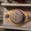
This is an example of a less frustrating in-house numbering - the equipment makers part number over-stamped rather than replacing the chip makers part number:
As others have said, it's almost certainly an in-house number, so there will be no specifications available for it - and the only people who could tell you what it actually is, are the manufacturers who ordered it with that number.
I wouldn't go as far as even a 'slim chance' of it been labelled underneath, as I've never seen one that was - and I've replaced a LOT of in-house components over the decades. Luckily, at least we had the service manuals, and while it gives you no details other than the in-house number, it's relatively easy to work out a suitable replacement if you have the circuit.
Its a Grass Medical instruments AM7 audio monitor..
I didn't find any info on the web as far as schematics.
I'm sure its the audio output.. I was curious on its rating.
There are several hits on the web on these amps for sale.. looks like small guitar practice amp . Nothing on the wattage draw on the back..
I assume its 3-5watts..small power transformer..I haven't set it up on a dummy load to see where sine wave clips yet.
I don't know the load ohmage.
I guess i just measure the dc ohms of the speaker.
It uses a Utah 8" whizzer cone speaker..
The speaker is a V8jc 157.. normally instead of 157 is a 8 or 3.2 for the speaker impedance .. Don't know if the 157 is the impedance or just indicates a special product for the manufacture just Iike the to3 case output.
I had this unit for a while . If you web search you'll see my old post in ARF looking for speaker specs. Very little info on the web on Utah speakers.. found roberts site with one catalog.
My request was just on the specs of the IC but looks like that's a dead end..
I appreciate all info and replies.
Doug
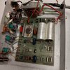
Post pictures of the entire board. As far as speaker impedances go, just measure the DC resistance, which should be about 3/4 of the impedance - so an 8 ohm speaker reads about 6 ohms resistance, and a 4 ohm one reads 3 ohms.
Are you suggesting the device you pictured is an IC, and not just a transistor?.
Speaker reads 13.3 ohms on my old Beckman. So maybe 16 ohm. Or 15.7
when I have time later this week take board out and if it's an ic find reference to what is connected to the pins .
PA61A - Power Operational Amplifier, 90V, 10A, "A" GradeThe PA61 and PA61A are high output current operational amplifiers designed to drive resistive, inductive
Speaker reads 13.3 ohms on my old Beckman. So maybe 16 ohm. Or 15.7
when I have time later this week take board out and if it's an ic find reference to what is connected to the pins .
Flip the board over and check the number of pins - if there's more than two, then it's an IC - but TO3 IC's are pretty unusual.
I see JRW has posted while I was typing, and it makes sense that's it's an (old) power opamp, rather than an actual audio amplifier, which would also explain the 16 ohm speaker.
Looking at the antique opamps in it, it's presumably a very old unit?.
Eight pins
Pin 1 is B+ pin 8 is B-
Pin 5 output wired direct to the speaker
The unit is made in 1977
I have had this for a while..
I have not turned it on.
I open old electronics up do a visual then power up slowly..I'll replace the speaker with a 15 ohm resistor on initial test.
I did test the speaker on another audio unit works good.
Most likely caps are bad.
I notice the 2 large caps have Grass name on them
I've had another thorough search but so far I've not been able to find any device that matches that pinout; most have power & ground on 3 & 6 or 2 & 7, with 1 as the output..
It's quite possible the data for that was just never scanned & only exists in old databooks - or its a custom IC.
Eight pins
Pin 1 is B+ pin 8 is B-
Pin 5 output wired direct to the speaker
The unit is made in 1977
I have had this for a while..
I have not turned it on.
I open old electronics up do a visual then power up slowly..I'll replace the speaker with a 15 ohm resistor on initial test.
Back in the day, capacitors were generally more reliable than they are now, and particularly on something like this, which doesn't use a switch-mode power supply. The VAST amount of capacitor failures are in switch-mode power supplies, where the high frequencies and high current pulses soon kill off poor quality capacitors.
I'll post more info on pins and voltages later..
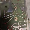
one thing I notice is the red marks on the solder joints on the thru hole connections.. Maybe it was from inspection marks ??
In the 1st picture in the 1980 catalog.. I did that wire bonding from the die to the carrier pads with a manual K&S wedge wire bonder.
I used 99.99% .0007od " gold wire.. It was at a research lab where they may proto types... I gave it up after I turned 68 yrs old..
Again I appreciate all replies , information, and this group.
Doug
This site uses cookies to help personalise content, tailor your experience and to keep you logged in if you register.
By continuing to use this site, you are consenting to our use of cookies.

")