Follow along with the video below to see how to install our site as a web app on your home screen.
Note: This feature may not be available in some browsers.
The gate only needs to be negative voltage with respect to the source.Thanks for the corrections on the circuit .The FET must act as a variable resistor controlling the +5V. Since it is an MPF102 it needs a negative voltage on the gate to work as a variable resistor. Right?
Thanks,
Another reason that the 7905 is destroyed or why it doesn't work.Also note that the pinout is different to the LM7805 - see the datasheets.
Hi Prprog,
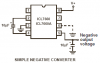
You probably don't need to generate a negative voltage.
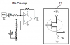
The gate voltage only needs to be negative with respect to
the source of the fet. If you apply a positive voltage to
the source you can make the voltage to the gate less
positive . . . You can generate this voltage with a zener
diode and a resistor and don't forget the decoupling
capacitor.
on1aag.
You have the drain and source mixed up.
The datasheet shows a wide range of voltage and current.
some MPF102 FETs turn on hard when the gate is positive a few volts and others are turned off. The voltage between the gate and the source (your red dot) is somewhere from 0.5V to 7.5V for a current of 0.2mA to flow.
So with the gate at 3V then the resistor from the source to ground and the spec's of your FET determine the output voltage.
Why do you want to make a very non-linear resistor with a FET?
The MPF102 FET is turned on completely when its gate voltage is the same as its source voltate. It is cutoff (0.2mA) when its gate voltage is 0.5V to 7.5V more negative than its source voltage. Each one is different.