Electro Tech is an online community (with over 170,000 members) who enjoy talking about and building electronic circuits, projects and gadgets. To participate you need to register. Registration is free. Click here to register now.
Welcome to our site! Electro Tech is an online community (with over 170,000 members) who enjoy talking about and building electronic circuits, projects and gadgets. To participate you need to register. Registration is free. Click here to register now.
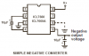
I want to used a FET as a voltage control resistor. How do I generate a negative voltage ? In this case I will used a microphone connected to an OpAmp amplifier. What I want is to connect the output of the opamp to the FET (but it needs to be negative).
You probably don't need to generate a negative voltage.
The gate voltage only needs to be negative with respect to
the source of the fet. If you apply a positive voltage to
the source you can make the voltage to the gate less
positive . . . You can generate this voltage with a zener
diode and a resistor and don't forget the decoupling
capacitor.
I draw a quick diagram (please excuse all the missing connection; it is out of proportions and/or possible errors). The OpAmp will be power by a different supply than the 5volts on the FET (sort like trying to isolate both). The Opamp will have a separate power supply and the 5 volts for the FET comes from a second power supply. Can I tie the ground from the OpAmp power supply to the ground of the 5 volts? The FET is a MPF102; will the OpAmp output generate "more negative" voltage so the FET acts as a variable resistor?
I need the OpAmp to amplify the Microphone output. The microphone is a dynamic Mic.
Thanks for the corrections on the circuit .The FET must act as a variable resistor controlling the +5V. Since it is an MPF102 it needs a negative voltage on the gate to work as a variable resistor. Right?
Like all Jfets, the MPF102 has a wide range of specs. when its gate voltage is the same as its source voltage its current could be anywhere from 2ma to 20mA.
If you want 0.2mA then its gate voltage could be anywhere from -0.5V to -7.5V.
You forgot to say what you are doing with the FET. An audio compressor? Then look in Google for an audio compressor circuit that uses a FET. The FET is in the negative feedback loop of the opamps to vary the gain of the opmp, not as an attenuator. The circuit automatically adjusts for the wide range of gate voltages for different FETs. The level across the FET is kept low (100mV max) for low distortion and the gate is fed some signal to also reduce distortion.
Thanks for the corrections on the circuit .The FET must act as a variable resistor controlling the +5V. Since it is an MPF102 it needs a negative voltage on the gate to work as a variable resistor. Right?
The gate only needs to be negative voltage with respect to the source.
If the gate is 0V and the source is +1V then the gate is negative with respect to the source.
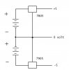
Hello guys, It's me and the same regulator problem again. I have powered my circuit with two 12V batteries as shown on the schematic, but 7905 exploded
You probably don't need to generate a negative voltage.
The gate voltage only needs to be negative with respect to
the source of the fet. If you apply a positive voltage to
the source you can make the voltage to the gate less
positive . . . You can generate this voltage with a zener
diode and a resistor and don't forget the decoupling
capacitor.
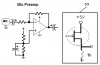
Using the attach diagram:
So if I have +5v on the source and put 3 volts on the gate (yellow dot) , which voltage will I get on the drain point - red dot (is that what is call?).
The datasheet shows a wide range of voltage and current.
some MPF102 FETs turn on hard when the gate is positive a few volts and others are turned off. The voltage between the gate and the source (your red dot) is somewhere from 0.5V to 7.5V for a current of 0.2mA to flow.
So with the gate at 3V then the resistor from the source to ground and the spec's of your FET determine the output voltage.
I found this circuit on the web. Can you help me understand the connections?
Correct me if wrong , Vin = +5V (could be), Vss = GND, Y and X I don't know?
Why do you want to make a very non-linear resistor with a FET?
The MPF102 FET is turned on completely when its gate voltage is the same as its source voltate. It is cutoff (0.2mA) when its gate voltage is 0.5V to 7.5V more negative than its source voltage. Each one is different.
Why do you want to make a very non-linear resistor with a FET?
The MPF102 FET is turned on completely when its gate voltage is the same as its source voltate. It is cutoff (0.2mA) when its gate voltage is 0.5V to 7.5V more negative than its source voltage. Each one is different.
I want to susbtitute a potentiometer with a voltage control resistor. The pot is normally connected to a PC port, so I am looking for a circuit that will do that. In this case the voltage will be generated by a microphone + OpAmp.
If the source voltage is +5 volts (from the PC game port) then "...when its gate voltage is 0.5v to 7.5V more negative..." means a voltage range of +4.5 to -2.5 ?
This site uses cookies to help personalise content, tailor your experience and to keep you logged in if you register.
By continuing to use this site, you are consenting to our use of cookies.