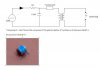
The spark is created using a piezo crystal. When you click the button, a little hammer hits the piece of crystal and it produces a high voltage electric current. This is the spark you use.
Piezo crystals are special in the sense that when they are flexed they produce electric current. Likewise, when an electric current is induced to them, they flex. This is how piezoelectric inducers work.
For more info, try searching piezoelectric effect on google or wikipedia.
Best regards,
michael11298