Continue to Site

Welcome to our site!

Electro Tech is an online community (with over 170,000 members) who enjoy talking about and building electronic circuits, projects and gadgets. To participate you need to register. Registration is free. Click here to register now.

  • Welcome to our site! Electro Tech is an online community (with over 170,000 members) who enjoy talking about and building electronic circuits, projects and gadgets. To participate you need to register. Registration is free. Click here to register now.

FT232R converter problem

Status
Not open for further replies.
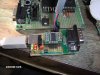
Got around to pasting a FT232R onto a proto board to give it a go. Windows XP recognized, it and was able to then install the latest driver.

Not having any luck communicating with a terminal, getting some gibberish, so TX from the PIC-->Max232 seems to be working. The odd thing is that a loopback test works just fine by shorting the RX and TX pins on the PIC side of the Max232.

In the Bray's terminal the transmit window indicates a 'frame error'. Played around with different baud rates. Tried device manager to change the ComPort buffer to smaller values, 64 bytes and latency to 4ms. Tried inverting the RX and TX in the Mprog (FTDI eeprom programmer), that didn't work.

Using a Prolific USB/Serial cable everything works as expected, so the software shouldn't be a problem.

Will say that the manual shows a 0.01uf polarized cap across the power pins on the bus powered setup that is implemented. Only able to come up with a ceramic cap for that, could that be a problem?

So checking to see if anyone has had this 'frame error', and where I might look to fix it.
 
It sounds like you are feeding the max232 into the FT232R, when you should not be? FT232R takes logic level on it's input/output. TX and RX should be connected directly to your controller.

If that's not the case, at least post as much information on your setup as you can. Happily the FT232R has been a chip I've never had a problem with.

Are you using this on a breadboard? USB 2.0 is very high speed and can be pretty sensitive to physical setup.
 
It sounds like you are feeding the max232 into the FT232R, when you should not be? FT232R takes logic level on it's input/output. TX and RX should be connected directly to your controller.
It works with TTL or RS232 here is thedata sheet link

The setup is per the bus powered configuration in the datasheet.

The FT232R is in a dip breakout board that socketed to a pad per hole pcb that's maybe 1.5"x2.5". So this is not on breadboard. Wiring is point to point.

It's weird that the loopback works, but when the Pic is connected, it doesn't. I am about to try the TTL route just to see if that would work. It's probably some sloppy soldering, or misplaced wire..........
 
Is the PIC adequately decoupled ? I.e.. 100nF minimum across the power pins as close as possible ?

It could also be that you have your baud rate incorrect on the PIC. I had a similar problem once and it turned out to be firstly inadequate decoupling then I found I had a 4Mhz xtal in 4xPLL mode by accident rather than the 10Mhz xtal in PLL mode.

It was only after I listened to the signal through a speaker than it clicked that the baud rate in was different to the baud rate out of the PIC
Actually 100nF is to much capacitor for the 4X PLL. PLLs are extraordinarily picky about power rail noise and the higher the value decoupling cap the WORSE the HF noise due to parasitic resistance and inductance.

Of course you still need larger ones for the low frequencies. 100-200pF as close as possible, 0.1uF fairly close, and a 10uF somewhere nearby.

Dan
 
Last edited:
It works with TTL or RS232 here is thedata sheet link

I'm missing this somewhere. I don't see in the datasheet where it says the inputs can handle RS232 levels. The max voltage for inputs is 0.5v over and under VCC. There is an example of driving the TTL side of a MAX232, but nothing about receiving +9/-9v from a MAX232.
 
I'm missing this somewhere. I don't see in the datasheet where it says the inputs can handle RS232 levels. The max voltage for inputs is 0.5v over and under VCC. There is an example of driving the TTL side of a MAX232, but nothing about receiving +9/-9v from a MAX232.

Perhaps the OP should post the circuit of what he's doing?, as far as I'm aware the FT232 will only accept TTL levels?. Because it's presumably intended to connect to a MAX232 it will also be the wrong polarity to connect directly to a PIC - which means you can't use the hardware USART unless you have a hardware inverter between them (both ways). If you use a software UART, it's simple to do the inversion in the software.
 
Some of the newer pics (eg 18F2550) have the inverter selectable in hardware. Very useful feature and, as the OP didn't indicate which pic he is using, it may be relevant.

Mike.
 
It's primary purpose is not to connect to a MAX232, that's just an option. There is a UART signal inversion option on the chip.

It can be connected to a hardware uC UART and uses standard UART signals fine in it's default operation mode. I have used this chip quite often for that purpose.
 
Last edited:
I've got the FT232R working fine and at ttl levels. Connected to another FTDI device. The Vinculum. If you hit it with true RS232 levels it may have put on a parachute and bailed out:eek:
 
Thanks one and all for your responses. The overwhelming consensus was to use it with the TTL interface. Wired it up and it worked, of course!

The idea of running it thru the Max232 was to mimic a USB/Serial cable. In the data sheet it does show hooking up to a RS232 converter, although I don't have their specifically recomended one. Will give another go when I have more time.

The Pic was a 16f877a on an Olimex Pic-40 board, so no problems there. A software serial routine was being used based on Nigel's assembly routine ported to GCBasic.

The FTDI link to the data sheet doesn't seem to work for me, so an attachment file for that.
 

Attachments

  • DS_FT232R_v104.pdf
    796.4 KB · Views: 660
I do not understand your confusion ... the datasheet you uploaded ...
8.4 USB to MCU UART Interface ... no level shifter

the level shifter is there only when you want rs232 levels or rs485 levels .. 8.1-8.3 but then again ft232 is not getting the rs232 levels but ttl levels, the rs232 are on the other side of the level shifter ... in order to talk to uC then you need another level shifter to get levels back to ttl.
 
The idea of running it thru the Max232 was to mimic a USB/Serial cable. In the data sheet it does show hooking up to a RS232 converter, although I don't have their specifically recomended one. Will give another go when I have more time.

I'm still not understanding what you were trying. The datasheet example show DSUB Connector -> MAX232 -> FT232R -> USB setup. The RS232 level signals are going out the DSUB. In this setup, it's exactly the same as your Prolific USB/Serial converter cable. What's the point of that, you already have a USB/Serial cable?

What it looks like you were trying to do is uC -> MAX232 -> FT232R -> USB in that case the RS232 level signals are going into the FT232R. That's not going to work no matter how you try to do it.
 
Last edited:
Level shifter, got it, really appreciate the extra eyeballs and thoughts. My brain was inserting 'transceiver' for some reason, ..uggh:eek:. Okay gonna get out the hacksaw and chop off the DB9 connector, hehe.

The excercise is really to learn a little about the FT232R chip and hopefully apply to a homegrown prototype board for some 40pin pics. I like the idea of using the USB port for power, and of course the serial communications.
 

Attachments

  • IM000149a.JPG
    IM000149a.JPG
    171.3 KB · Views: 501
Cool. I've found this chip very useful. I've even written some programs using my limited C# skills that use the DLL directly and interface with my projects.
 
Level shifter, got it, really appreciate the extra eyeballs and thoughts. My brain was inserting 'transceiver' for some reason, ..uggh:eek:. Okay gonna get out the hacksaw and chop off the DB9 connector, hehe.


MAX232 (3223...) is level shifter, it just takes few 0-5V or 0-3V inputs and shifts the level for them to -9V - +9V .... it also takes few lines with levels of -9 - +9 and shifts them to 0-5V (0-3V)...

The -9 - +9 V side is RS232 and goes to the DB9, the 0-5 (0-3)V side is for ft232, microcontroller etc ... if you need to communicate with PC then you need to shift level to RS232 (-9, +9) but if you talk between two chips, no need to shift the levels to -+9 and then shift them back to 0,5(3) ... just tie them directly... now, it might be correct to call max232 transceiver (my english is not that good so cannot bet on it) but what it does is level shifting.

ft232 is cool chip although i prefere the usb to parallel versions over usb to serial .. for testing **broken link removed** are great :)


The MAX232 also inverts the signal.

Mike.
 
Status
Not open for further replies.

Latest threads

New Articles From Microcontroller Tips

Back
Top