Continue to Site

Welcome to our site!

Electro Tech is an online community (with over 170,000 members) who enjoy talking about and building electronic circuits, projects and gadgets. To participate you need to register. Registration is free. Click here to register now.

  • Welcome to our site! Electro Tech is an online community (with over 170,000 members) who enjoy talking about and building electronic circuits, projects and gadgets. To participate you need to register. Registration is free. Click here to register now.

Ds1307 RTC Power Problem with battery

Saeedk9574

New Member
Hi everyone,
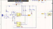
Whenever I apply voltage from source to the ds1307 RTC it works well but as soon as I connect it to CR2032 battery it gets stuck and Time does not work. I have checked the voltage of battery which is 3v but after resistance the provided voltage on ds1307 IC is about 1.5v. Accordingly, ds1307 needs minimum 2v. This is the circuit schematic diagram I took on the Internet and I did not design it by myself so I suppose the circuit is OK, but I do not know where the problem is.
 

Attachments

  • Screenshot (185).png
    Screenshot (185).png
    91.8 KB · Views: 118
The DS1307 is designed to be connected directly to the battery. R9 should be 0 Ohms. The current taken by the DS1307 should only be around 350 nA, and R9 will reduce the voltage by about 0.2 V but if the current taken by the DS1307 has any peaks, the voltage will drop further.

R10 will reduce the voltage to the DS1307 by taking extra current and giving a much larger voltage drop on R9 (unless it has been changed). R10 will also discharge the battery and take nearly 10 times as much current as the DS1307.

R5 and D3 provide a really crude and possibly dangerous recharging circuit for the battery. A CR2032 is not rechargeable so that circuit could cause damage to the battery.

I suggest that you connect a new CR2032 to pin 3 of the DS1307, with nothing else connected to that pin, like the datasheet from Analog shows:-

https://www.analog.com/media/en/technical-documentation/data-sheets/DS1307.pdf

A CR2032 has a capacity of around 200 mAh. The DS1307 takes about 350 nA to run the crystal. The battery will be discharged in somewhere over 50 years, although the battery will degrade faster than that. You don't need a recharging circuit.
 
The DS1307 is designed to be connected directly to the battery. R9 should be 0 Ohms. The current taken by the DS1307 should only be around 350 nA, and R9 will reduce the voltage by about 0.2 V but if the current taken by the DS1307 has any peaks, the voltage will drop further.

R10 will reduce the voltage to the DS1307 by taking extra current and giving a much larger voltage drop on R9 (unless it has been changed). R10 will also discharge the battery and take nearly 10 times as much current as the DS1307.

R5 and D3 provide a really crude and possibly dangerous recharging circuit for the battery. A CR2032 is not rechargeable so that circuit could cause damage to the battery.

There's a rechargeable version (LIR2032) with the exact same footprint, and it's commonly used in the cheap Chinese modules.

I suggest that you connect a new CR2032 to pin 3 of the DS1307, with nothing else connected to that pin, like the datasheet from Analog shows:-

https://www.analog.com/media/en/technical-documentation/data-sheets/DS1307.pdf

A CR2032 has a capacity of around 200 mAh. The DS1307 takes about 350 nA to run the crystal. The battery will be discharged in somewhere over 50 years, although the battery will degrade faster than that. You don't need a recharging circuit.

I imagine the circuit he's using has been copied from one of the cheap Chinese modules, I've just checked some DS1302 ones I have here, and they have two resistors on the board, labelled 514 and 155 - I've not followed the traces, but presumably they are the two incorrect resistors shown in the diagram above. The batteries on them are rechargeable LIR2032's - I've also got some DS3231 modules, and those use the non-rechargeable CR2032's.

Historically, in TV's, VCR's etc. rechargeable backup batteries regularly failed, and some manufacturers produced upgrades for them, where you removed the charging resistor, and fitted a non-rechargeable battery instead.

I certainly agree that the two spurious resistors will completely mess up the operation of the battery backup, quite bizarre really?.
 
The datasheet is abundantly clear about the Vbat connection. Nothing bizzare about it.
 
measuring battery voltage under no load will give you false readings. If the battery is connected to pin 3 and then measures 1.5v then its depleted. As Nigel has pointed out, that circuit is a crass charge circuit for a lithium battery.. I use that exact same circuit and they battery charges quite well.
 
measuring battery voltage under no load will give you false readings. If the battery is connected to pin 3 and then measures 1.5v then its depleted. As Nigel has pointed out, that circuit is a crass charge circuit for a lithium battery.. I use that exact same circuit and they battery charges quite well.
Interestingly, while I was checking my modules I measured the battery - the CR2032 on the DS3231 module reads fine, the LIR2032 on the DS1302 module reads 0V :D

I've had them both a good few years, so it shows which lasts best.
 
I appreciate all of you for sharing your opinions. This circuit is used in ds1307 module, so I supposed the circuit would be fine. you can see the original module circuit here.
DS1307-RTC-Module-Schematic.png
 
It's a horrible circuit as sold on Ebay!! I bought one of these modules as they are as cheap as chips (cheaper actually).
Apart from the problems mentioned above I found another interesting one when running without a battery, the Vbat pin is also a threshold voltage for I2C lockout and unless there is a bleed in R1 (I used 10Meg) Vbat rises to VCC due to chip leakage & consequentially I2C is locked out. This resistor does load the battery (300nA) and if I had a higher value in my junkbox I would have used it on the basis the leakage is probably <20nA.

In case your wondering why go to this trouble I wanted to be able to change the battery in situ whilst the device was still operating from VCC.
 

Latest threads

New Articles From Microcontroller Tips

Back
Top