Continue to Site

Welcome to our site!

Electro Tech is an online community (with over 170,000 members) who enjoy talking about and building electronic circuits, projects and gadgets. To participate you need to register. Registration is free. Click here to register now.

  • Welcome to our site! Electro Tech is an online community (with over 170,000 members) who enjoy talking about and building electronic circuits, projects and gadgets. To participate you need to register. Registration is free. Click here to register now.

Frequency problem PWM IC 3843

Status
Not open for further replies.
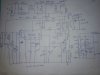
Hello I have built an smps charger ( from 220 VAC) using UC3843B. I am supplying power to it from a different 12V battery temporarily because I am planning to supply it from an auxiliary winding. The transformer I got from an old smps inverter. I am running the oscillator at 64 KHZ freq at pin 4.
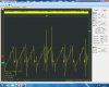
As I switch the circuit on, the output current I read is 5A where it is designed to output 10A. And the freq I measured at pin 4 is 120 KHZ and at the output pin it is 25 KHZ only. I think this makes the transformer to create a hissing sound. Also when I switch off the mains the output and oscillator freq becomes same 64KHZ which is the desired freq.
I also have added slope compensation circuit at pin 3 as in the datasheet. Sometimes I removed it but nothing changed. What I am missing? I am lost. Please help!
 
Could you post a schematic of your whole circuit please? I can't quite follow what's going on from your description.
 
I don't have simulation software. But this is somewhat a mixture of reverse engineered smps, online suff, datasheets and app notes. Please have a look. Thanks!
 

Attachments

  • 20160921_192148.jpg
    20160921_192148.jpg
    209 KB · Views: 300
Just some questions relating to your measurements:
The 5A you measured - does that refer to the output to the battery? What's the voltage when it's delivering 5A?
How did you make your frequency measurements? If you made them using a 'scope, perhaps you can post pictures of the trace. If you made them using a frequency meter, be aware that frequency meters can easily be confused by complex waveforms.
 
Do you not need a step-down transformer on the mains input. I can't see that the IC can handle rectified mains voltage unless i'm missing something about the operation of the circuit.

[Edit] on looking into it further i withdraw the comment above. Although I've not checked component values the circuit does look correct.
 
Last edited:
I am measuring freq with a digital multimeter.
Frequency counters (digital multi-meters) can not count accurately complex waveforms.
Here are two wave forms (from book) showing transformer ring on the output of a transformer. The multimeter does not what to measure 100khz switching or mhz ring.
upload_2016-9-23_8-37-19.png
 
When I touch 3rd pin with the other multimeter lead the output freq increases to somewhat 40KHZ and the current also increases to about 8A and the hissing sound reduces to some amount.
 
Hissing sound on a smps in my experience is either poor primary - secondary coupling within the transformer, or poor transient response causing oscillations within the feedback circuit, these however with your circuit are unlikely as your using a pre-made transformer, and the uc3843 is a current mode device making feedback oscillations less likely.
I suspect something is going on with the transformer, do you know the saturation current?, do you know the airgap?, the topology of the circuit the donor transformer came from could well be totally different than your application.
I see you have ringing suppression on both the pri and sec windings, how did you work these values out?
 
Beg, borrow or buy an osciloscope.
SMPS circuits are one of those that you really require one of them, for in-depth troubleshooting.
 
I absolutely agree with Schmitt - this will be extremely difficult without an oscilloscope. If you possibly can, get a high-voltage x100 probe as well (I don't know about others, but I'm not comfortable using a 600V x10 probe on SMPS primaries, due to the high voltage/high frequency combination).
 
A common practice for designing smps rc snubbers is to find the resonant freq of the parasitic capacitance of the switching device, and the leakage inductance of the transformer, then monitor the effect different capcitors have on the transients.
The only way you can do this properly is with a 'scope.
Funnily enough I'm working on a smps with a uc3843 right now, heres a screen shot, I can tell that my switching transients are really noisy and the transients are most likely too high for the mosfet.

'scope.png
 

Attachments

  • 'scope.png
    'scope.png
    183.7 KB · Views: 134
Sorry for late reply. I found the problem was the output filter capacitor which was not working at all. And this caused the rectified output to go directly to the feedback opto. And the circuit would go into the "voltage control mode".

Thank you all for your suggestions!
 
I'm glad that you have corrected the problem.

For the benefit of all members of this forum, would you describe in detail what you mean by "the output filter capacitor which was not working at all" ?
What was wrong with the capacitor itself? Or was it a poor solder joint?
 
If you are saying that the feedback connection being placed nearer to the rectifier than the capacitor causes issues then the pcb track or wire from the rectifier to the cap isnt heavy enough, ie not enough copper ansd you are getting voltage drop issues, or if the cap is long way from the bridge maybe inductive issues.
 
Status
Not open for further replies.

Latest threads

New Articles From Microcontroller Tips

Back
Top