Continue to Site

Welcome to our site!

Electro Tech is an online community (with over 170,000 members) who enjoy talking about and building electronic circuits, projects and gadgets. To participate you need to register. Registration is free. Click here to register now.

  • Welcome to our site! Electro Tech is an online community (with over 170,000 members) who enjoy talking about and building electronic circuits, projects and gadgets. To participate you need to register. Registration is free. Click here to register now.

Forward power and reflected power and transmitter and antenna matching

Status
Not open for further replies.
I want Nigel and RadioRon to double check but....
I am starting to understand.
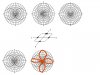
If only two elements were working and you stood above the antenna looking down you would get a pattern like the left one. (AB)
If the other two elements were working then the middle picture would be correct. (CD)
If all four elements were working then the two patters will add and you should get the pattern on the right. (ABCD)

The book says; If you look at the radiation from the side of the antenna, where 0=up, 90=N, 180=down, 270=south, the pattern is on the bottom left. I think it is what I make on the bottom right. Now I need to defend my position. If element A and B are driven in phase and are 1 wave length apart, then the energy from A will reach B and add (2X). At about 45 degrees the energy from A will meat the energy from B at 1.5 (x.5) wave lengths off and subtract (o). At 0 degrees, and 180 the energy from A and B will add (2X). I can not think about this more I need to leave for work in 8 hours.

I do worry that your antenna is not 50 ohms. I need to get out my ARRL hand book and see if I can find an example. Two dipoles 1 apart, driven in phase what is the impedance? What is the pattern?
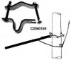
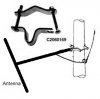
 

Attachments

  • Image1.jpg
    Image1.jpg
    132.3 KB · Views: 332
Last edited:
Hello guys. I finally got a response from the guy who sold me the antenna. He said the way I did it is wrong. They should be mounted all vertically above each other with a separation of 260cm (Just like some of you pointed out). Like this photo here:


Also look at the pdf I attached.
 

Attachments

  • Asit antenna.jpg
    Asit antenna.jpg
    188.2 KB · Views: 360
  • PLS 1 600 w antenna.pdf
    513.5 KB · Views: 948
YES!!!!!!!!!!!!!!!!
Now I need to talk about you guy wires. No time now....off to work.
 
YES!!!!!!!!!!!!!!!!
Now I need to talk about you guy wires. No time now....off to work.

Take your time my friend.

But you know, how we are going to mount these dipoles vertically with the brackets provided is beyond me. They should have provided different brackets. Now, we will have to make something up.
 
Take your time my friend.

But you know, how we are going to mount these dipoles vertically with the brackets provided is beyond me. They should have provided different brackets. Now, we will have to make something up.

Why is it any different?, in either case you have a horizontal beam which needs connecting to the vertical mast.
 
Forget it Nigel. It is not something to worry about really. If necessary, we will just wield them somehow into place.

My concern is why you have a problem, as I see it the aerial is a vertical dipole, mounted on a horizontal beam.

Mounting it incorrectly horizontally (as you did) is surely just a matter of rotating the vertical dipole 90 degrees, with the beam staying horizontal.
 
I am back for 10 minutes. Now that you will build the antenna vertically it will be tall. You should not have metal wires going through your antenna. Below the bottom element metal wires are OK. (10 feet below) I have fiberglass rods with eye holes on each end. From ground to a point below the bottom element is wire, then I change to fiberglass so the RF is not in the wire support. The top of the support wires needs to be non conductive. Because your pole is not strong you need many wires. Rope stretches too much. My antenna say how much pressure a 100mile/hour wind pushes per element. With some math you can see how strong the supports must be.

I made a big mistake many years ago. The antenna tower is on top of a 7 story building. The wires, cables, are strong and I used good cable clamps, 3 on each place. I used eye hooks every where. At the roof of the building I used "J" hooks. One day in a very strong wind I went up to see how things are. The wind pushed the tower to one side so much that the down wind cable has no tension. The cable came off the J hook because there was no tension. I connected back the cable and added some wire to keep the cable in place. About 10 minutes the wind reversed direction. I saved the tower. The next day we replaced the J hooks with eye screws.

I hope never to be on top of a seven story building in a 80 m/h wind again.
 
My concern is why you have a problem, as I see it the aerial is a vertical dipole, mounted on a horizontal beam.

Mounting it incorrectly horizontally (as you did) is surely just a matter of rotating the vertical dipole 90 degrees, with the beam staying horizontal.

My concern is why you have a problem, as I see it the aerial is a vertical dipole, mounted on a horizontal beam.

Mounting it incorrectly horizontally (as you did) is surely just a matter of rotating the vertical dipole 90 degrees, with the beam staying horizontal.

Are you saying we can rotate the element? I'm now away but I don't remember the antenna having any rotating mechanism at all.
 
I am back for 10 minutes. Now that you will build the antenna vertically it will be tall. You should not have metal wires going through your antenna. Below the bottom element metal wires are OK. (10 feet below) I have fiberglass rods with eye holes on each end. From ground to a point below the bottom element is wire, then I change to fiberglass so the RF is not in the wire support. The top of the support wires needs to be non conductive. Because your pole is not strong you need many wires. Rope stretches too much. My antenna say how much pressure a 100mile/hour wind pushes per element. With some math you can see how strong the supports must be.

I made a big mistake many years ago. The antenna tower is on top of a 7 story building. The wires, cables, are strong and I used good cable clamps, 3 on each place. I used eye hooks every where. At the roof of the building I used "J" hooks. One day in a very strong wind I went up to see how things are. The wind pushed the tower to one side so much that the down wind cable has no tension. The cable came off the J hook because there was no tension. I connected back the cable and added some wire to keep the cable in place. About 10 minutes the wind reversed direction. I saved the tower. The next day we replaced the J hooks with eye screws.

I hope never to be on top of a seven story building in a 80 m/h wind again.

The wires are not conductive. One problem I'll face now though is that our mast consists of several pieces (Telescopic mast). The final piece will not be enough to mount the four antennas with the required spacing. So, we will need to mount two antennas on the final piece and the other two on the piece before that. That will make spacing them too difficult.

You know, if we bring down the mast, the last piece will have to go down and get inside the previous one. The only other way is to use a crane to left somebody who can do the mounting. Tough.
 
Last edited:
Are you saying we can rotate the element? I'm now away but I don't remember the antenna having any rotating mechanism at all.

They don't need it, the horizontal beam is clamped to the mast - simply twist the beam 90 degrees, and the dipole at the end will be vertical - as intended.

Think of it as a capital T, with the bottom of the T the fixing point, rotating the bottom part rotates the top.
 
They don't need it, the horizontal beam is clamped to the mast - simply twist the beam 90 degrees, and the dipole at the end will be vertical - as intended.

Think of it as a capital T, with the bottom of the T the fixing point, rotating the bottom part rotates the top.

That will also rotate the provided brackets. How can I make the brackets close in the mast or bite it you may say??

This photo might explain a little:
 

Attachments

  • service-bracket-mast-1.jpg
    service-bracket-mast-1.jpg
    11.5 KB · Views: 322
This is easier to understand(the antenna and the brackets are fixed together):
 

Attachments

  • service-bracket-mast-1.jpg
    service-bracket-mast-1.jpg
    17.4 KB · Views: 326
Green is antenna.
Red is telescoping pole.
Blue is new pole that attached to top of telescoping pole and the bottom slides up pole.

I hope this idea helps.
 

Attachments

  • Image2.jpg
    Image2.jpg
    38.3 KB · Views: 331
Last edited:
Green is antenna.
Red is telescoping pole.
Blue is new pole that attached to top of telescoping pole and the bottom slides up pole.

I hope this idea helps.

Yeeees, I was exactly thinking about the same idea. I was even planning to draw it, post it here and send it to my technician. Now, I'll just send them your drawing ^_^

Thanks a million for all the help ron, Nigel and everybody else. This is seriously the best forum of all time. Can't live without it. I will post results when I'm done.
 
This is easier to understand(the antenna and the brackets are fixed together):

How are they fixed together?, it's the strangest idea I've ever seen, and looks a very weak connection.

Did you fix it on?, I can't imagine it came like that?.

I presume it's designed (like pretty well everything else) to be attached using a 'universal clamp', which joins two poles at right angles. which would allow you to set any polarity you want.

This is an example of one specific type, for a particular make of TV aerial.

https://www.dhwelectronics.com/Aerial_Fixings_006000100040/T143BS_Universal_Aerial_Clamp

And this is a more general purpose one.
 
Status
Not open for further replies.

Latest threads

Back
Top